DESCRIPTION
The
µ
PG2160T5K is a GaAs MMIC for L, S-band SPDT (Single Pole Double Throw) switch which was developed
for mobile phone and other L, S-band applications.
This device can operate frequency from 0.5 to 3.0 GHz, with low insertion loss and high isolation.
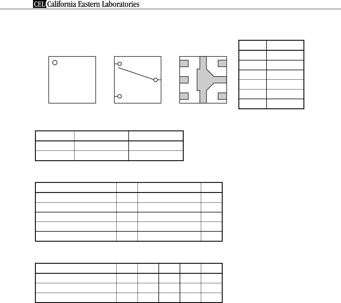
This device is housed in a 6-pin plastic TSSON (
Thin Shrink Small Out-line Non-leaded) package, and is suitable
for high-density surface mounting.
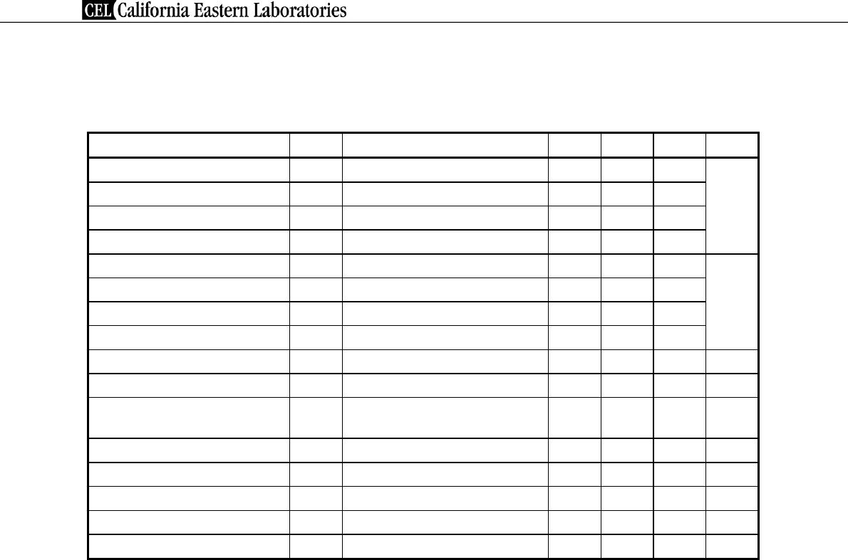
FEATURES
• Supply voltage : VDD = 2.4 to 2.8 V (2.6 V TYP.)
• Switch control voltage : V
cont (H) = 2.4 to VDD (2.6 V TYP.)
: V
cont (L) = −0.2 to 0.2 V (0 V TYP.)
• Low insertion loss : L
ins1 = 0.30 dB TYP. @ f = 0.5 to 1.0 GHz, VDD = 2.6 V, Vcont (H) = 2.6 V, Vcont (L) = 0 V
: L
ins2 = 0.35 dB TYP. @ f = 1.0 to 2.0 GHz, VDD = 2.6 V, Vcont (H) = 2.6 V, Vcont (L) = 0 V
: L
ins3 = 0.40 dB TYP. @ f = 2.0 to 2.5 GHz, VDD = 2.6 V, Vcont (H) = 2.6 V, Vcont (L) = 0 V
: L
ins4 = 0.50 dB TYP. @ f = 2.5 to 3.0 GHz, VDD = 2.6 V, Vcont (H) = 2.6 V, Vcont (L) = 0 V
• High isolation : ISL1 = 25 dB TYP. @ f = 0.5 to 1.0 GHz, V
DD = 2.6 V, Vcont (H) = 2.6 V, Vcont (L) = 0 V
: ISL2 = 18 dB TYP. @ f = 1.0 to 2.0 GHz, V
DD = 2.6 V, Vcont (H) = 2.6 V, Vcont (L) = 0 V
: ISL3 = 17 dB TYP. @ f = 2.0 to 2.5 GHz, V
DD = 2.6 V, Vcont (H) = 2.6 V, Vcont (L) = 0 V
: ISL4 = 13 dB TYP. @ f = 2.5 to 3.0 GHz, V
DD = 2.6 V, Vcont (H) = 2.6 V, Vcont (L) = 0 V
• Handling power : P
in (0.1 dB) = +21.0 dBm TYP. @ f = 2.0/2.5 GHz, VDD = 2.6 V, Vcont (H) = 2.6 V, Vcont (L) = 0 V
• High-density surface mounting : 6-pin plastic TSSON package (1.0 × 1.0 × 0.37 mm)
APPLICATIONS
• L, S-band digital cellular or cordless telephone
• W-LAN, WLL and Bluetooth
TM
etc.
ORDERING INFORMATION
Part Number Order Number Package Marking Supplying Form
µ
PG2160T5K-E2
µ
PG2160T5K-E2-A 6-pin plastic TSSON
(Pb-Free)
Note
G4 • Embossed tape 8 mm wide
• Pin 1, 6 face the perforation side of the tape
• Qty 5 kpcs/reel
Note With regards to terminal solder (the solder contains lead) plated products (conventionally plated), contact
your nearby sales office.
Remark To order evaluation samples, contact your nearby sales office.
Part number for sample order:
µ
PG2160T5K-A
2006
Caution Observe precautions when handling because these devices are sensitive to electrostatic discharge.
L, S-BAND SINGLE CONTROL SPDT SWITCH
GaAs INTEGRATED CIRCUIT
µ
PG2160T5K
Document No. PG10635EJ01V0DS (1st edition)
Date Published September 2006 NS CP(K)