CAT1021, CAT1022, CAT1023
http://onsemi.com
7
DEVICE OPERATON
Reset Controller Description
The CAT1021/22/23 precision RESET controllers ensure
correct system operation during brownout and power
up/down conditions. They are configured with open drain
RESET outputs.
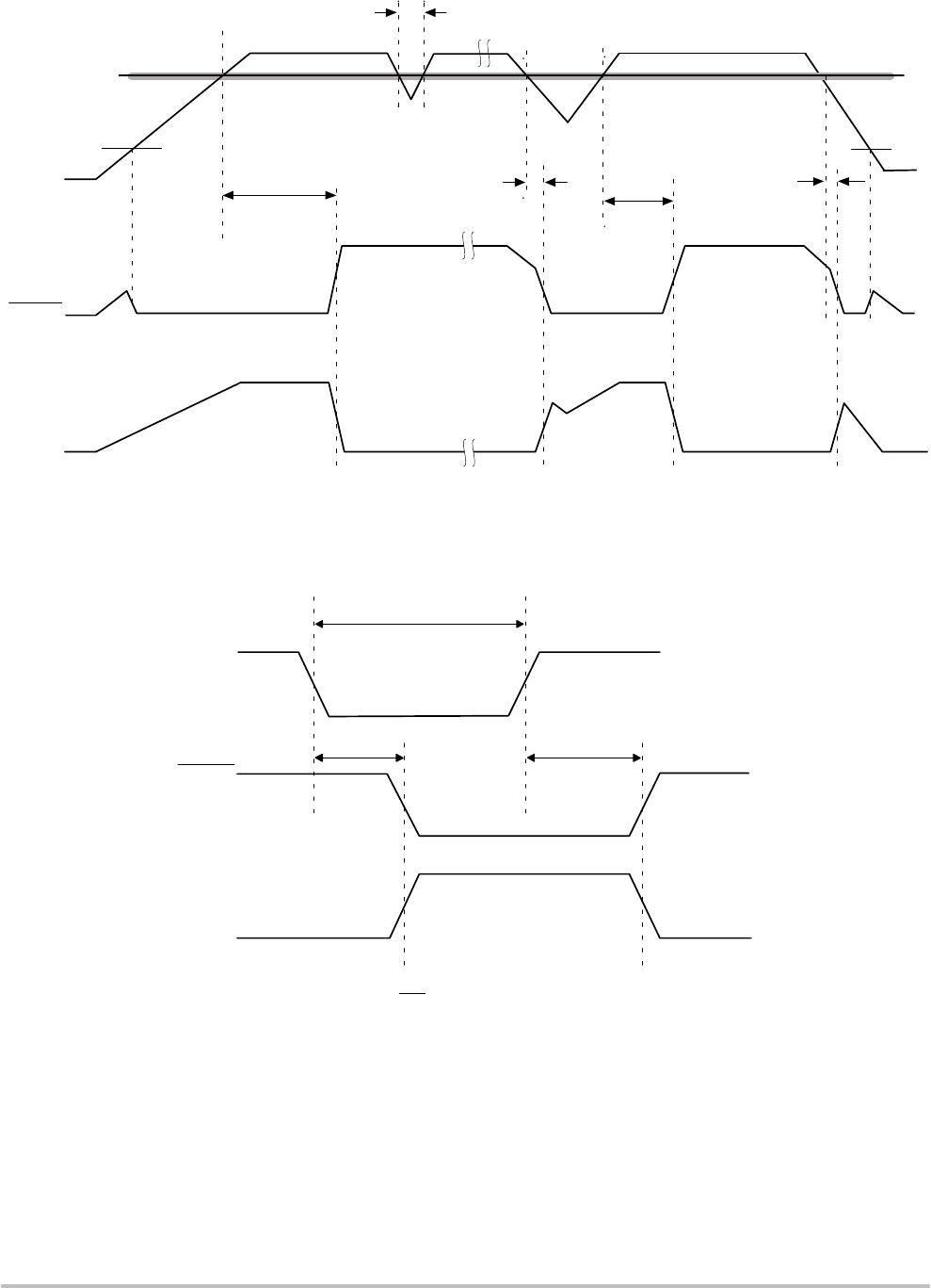
During power−up, the RESET outputs remain active until
V
CC reaches the VTH threshold and will continue driving the
outputs for approximately 200 ms (t
PURST) after reaching
V
TH. After the tPURST timeout interval, the device will cease
to drive the reset outputs. At this point the reset outputs will
be pulled up or down by their respective pull up/down
resistors.
During power−down, the RESET outputs will be active
when V
CC falls below VTH. The RESET output will be valid
so long as V
CC is >1.0 V (VRVALID). The device is designed
to ignore the fast negative going V
CC transient pulses
(glitches).
Reset output timing is shown in Figure 1.
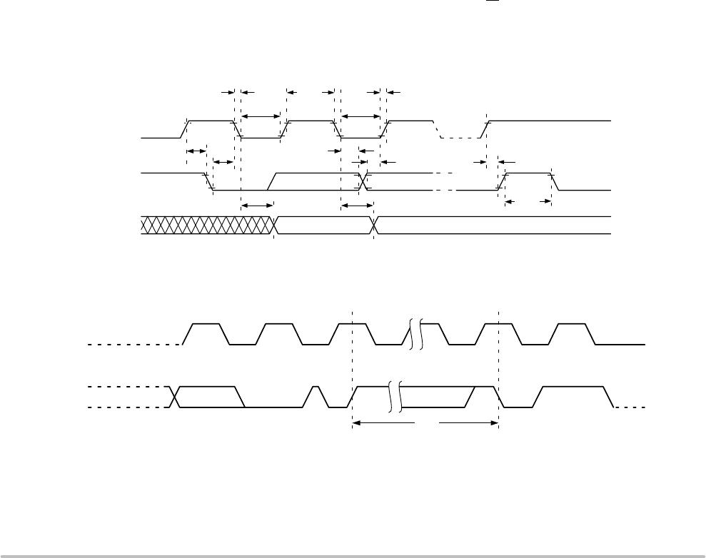
Manual Reset Operation
The RESET pin can operate as reset output and manual
reset input. The input is edge triggered; that is, the RESET
input will initiate a reset timeout after detecting a high to low
transition.
When RESET
I/O is driven to the active state, the 200 ms
timer will begin to time the reset interval. If external reset is
shorter than 200 ms, Reset outputs will remain active at least
200 ms.
The CAT1021/22/23 also have a separate manual reset
input. Driving the MR
input low by connecting a pushbutton
(normally open) from MR
pin to GND will generate a reset
condition. The input has an internal pull up resistor.
Reset remains asserted while MR
is low and for the Reset
Timeout period after MR
input has gone high.
Glitches shorter than 100 ns on MR
input will not generate
a reset pulse. No external debouncing circuits are required.
Manual reset operation using MR
input is shown in Figure 2.
Hardware Data Protection
The CAT1021/22/23 supervisors have been designed to
solve many of the data corruption issues that have long been
associated with serial EEPROMs. Data corruption occurs
when incorrect data is stored in a memory location which is
assumed to hold correct data.
Whenever the device is in a Reset condition, the
embedded EEPROM is disabled for all operations,
including write operations. If the Reset output(s) are active,
in progress communications to the EEPROM are aborted
and no new communications are allowed. In this condition
an internal write cycle to the memory can not be started, but
an in progress internal nonvolatile memory write cycle can
not be aborted. An internal write cycle initiated before the
Reset condition can be successfully finished if there is
enough time (5ms) before V
CC reaches the minimum value
of 2V.
In addition, the CAT1021 includes a Write Protection
Input which when tied to V
CC will disable any write
operations to the device.
Watchdog Timer
The Watchdog Timer provides an independent protection
for microcontrollers. During a system failure,
CAT1021/22/23 devices will provide a reset signal after a
time−out interval of 1.6 seconds for a lack of activity. The
CAT1023 is designed with the Watchdog timer feature on
the WDI pin. The CAT1021 and CAT1022 monitor the SDA
line. If WDI or SDA does not toggle within a 1.6 second
interval, the reset condition will be generated on the reset
outputs. The watchdog timer is cleared by any transition on
a monitored line.
As long as reset signal is asserted, the watchdog timer will
not count and will stay cleared.