ASRM2JA47R0

Rev Date: 02/29/2016 1 www.seielect.com
This specification may be changed at any time without prior notice marketing@seielect.com
Please confirm technical specifications before you order and/or use.
ASR/ASRM Series
Anti-Surge Resistor
Stackpole Electronics, Inc.
Resistive Product Solutions
0.126
± 0.008 0.073 ±
0.008 1.102 ± 0.118 0.018
± 0.002 inches
3.20
± 0.20 1.85 ±
0.20 28.00 ± 3.00 0.45
± 0.05 mm
0.236 ± 0.012 0.091
± 0.008 1.102 ± 0.118 0.022 ± 0.002
inches
6.00 ± 0.30
2.30 ± 0.20 28.00 ± 3.00 0.55
± 0.05 mm
0.354
± 0.039 0.118 ±
0.020 1.102 ± 0.118 0.028 ± 0.002 inches
9.00 ± 1.00
3.00 ± 0.50 28.00 ± 3.00 0.70 ±
0.05 mm
0.433 ± 0.039 0.157 ± 0.020 1.102
± 0.118 0.031 ± 0.002 inches
11.00 ± 1.00 4.00 ± 0.50
28.00 ± 3.00 0.80 ± 0.05 mm
0.591 ± 0.039 0.197 ± 0.020 1.378 ± 0.118
0.031 ± 0.002 inches
15.00 ± 1.00 5.00 ± 0.50
35.00 ± 3.00 0.80 ± 0.05 mm
0.591 ± 0.039 0.197 ± 0.020 1.378 ± 0.118 0.031
± 0.002 inches
15.00 ± 1.00 5.00 ± 0.50 35.00 ± 3.00 0.80
± 0.05 mm
Body Diameter
1340
Lead Length(Bulk)
Weight
(mg/pc)
110
330
570
C
ASR14
210
1340
ASRM2
ASRM12
ASR1
Type / Code
Unit
ASRM14
ASRM1
A
Body Length
D
Lead Diameter
B
DC 1600V DC 2000V 1000V 3.3 - 510K
AC 1150V AC 1500V 3000V 560K - 12M
5000V 3.3 - 510K
10000V 560K - 12M
5000V 3.3 - 510K
10000V 560K - 12M
5000V 3.3 - 510K
10000V 560K - 12M
5000V 3.3 - 510K
10000V 560K - 12M
(1) Lesser of PR or maximum working voltage.
(2) 10 discharges from a 0.01µF capacitor every 5 seconds.
500VAC
500VAC
500VAC
500VAC
5000V
4000V
5000V
4000V
5000V
0.25W
0.25W
1W
1W
4000V
ASRM2
2W
Surge
Withstanding
Type / Code
Power Rating
(Watts) @ 70ºC
Maximum
Working
Voltage
Maximum
Overload
Voltage
ASRM1
0.5W
2000V
2500V
ASRM14
ASR14
500V
1000V
ASR1
Ohmic Range (Ω) and
Tolerance
5%
ASRM12
22M
Dielectric
Withstand Voltage
200VAC
400VAC
2000V
100K
-
(1)
(2)
Features:
Excellent anti-surge characteristics
Stable characteristics through the resistance range
Good alternative to carbon composition resistors
Applications include power supplies, CRT’s, and anti-
surge circuits
Cut and formed product is available on select sizes;
contact factory for details
Flameproof coating per UL94 V-0
RoHS compliant / lead-free
Electrical Specifications
Rev Date: 02/29/2016 2 www.seielect.com
This specification may be changed at any time without prior notice marketing@seielect.com
Please confirm technical specifications before you order and/or use.
ASR/ASRM Series
Anti-Surge Resistor
Stackpole Electronics, Inc.
Resistive Product Solutions
All Other Sizes:
-1800~0 ppm/ºC
Change of resistance
± (0.5%+0.05Ω)
No mechanical damage
Tensile:
Tensile strength: 10N
Bend:
Bending strength: 5N
Test
Test Result
Test Method
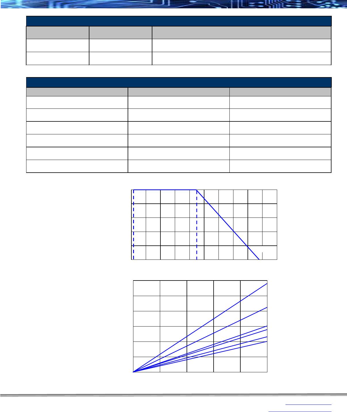
At 70 ± 2ºC, apply rated DC voltage 1.5 ON, 0.5 hour OFF for 1000 hours and
leave in room temperature for one hour after test.
Change of resistance
± (5%+0.05Ω)
Endurance at 70ºC
The resistor shall be subjected to 5 continuous cycle,
each as shown in the table below:
Change of resistance
± (1%+0.05Ω)
Rapid Change of
Temperature
Apply 1.5mm amplitude vibration to three directions perpendicular to each
other 2 hours each, total 6 hours. Vibrating frequency is 10Hz-55Hz-10Hz
cycle in 1 minute sweeping and repeat cycle
Change of resistance
± (1%+0.05Ω)
Vibration
Change of resistance
± (5%+0.05Ω)
Damp Heat,
Steady State
In the chamber having temperature of 40 ± 2ºC and relative humidity of
93 ± 3%, apply one percent of the rated power, 1.5 hour ON, 0.5 hour OFF
for 1000 hours and leave in room temperature for one hour after test.
Robustness of
Terminations
Dip the lead into a solder bath having a temperature of 260ºC ± 5ºC up
to 1.5 ± 0.5 mm from the body of the resistors and hold it for 10 ± 0.5 seconds
and leave in room temperature for one hour after test.
Change of resistance
± (1%+0.05Ω)
Resistance to
Soldering Heat
More than 95% of the
surface of the lead will be
covered by new solder
Dip the lead into a solder bath having a temperature of 245ºC ± 5ºC up
to 1.5 ± 0.5 mm from the body of the resistors and hold it for 5 ± 0.5 seconds.
Solderability
The body of the resistor is fixed, a static load is added in the direction of
drawing out of the terminal, and it maintains it for 10 ± 1 seconds.
Component body will be fixed so that terminals are perpendicular to the floor.
A static load specified below shall be applied to the terminal acting in a
direction away from the body. The body of piezoelectric oscillator will be
inclined through an angle of 90ºC and then retuned to its initial position
in 2 or 3 seconds
Change of resistance
± (0.5%+0.05Ω)
Soak in a Isopropyl alcohol for 5 minutes. After drying up for 5 minutes, the
stress of 5N is added with the absorbent cotton. Five round trips at the rate of
one round trip a second.
There will be no damage
on the insulating surface
Solvent Resistance
Apply 2.5 times rated voltage or max overload voltage whichever is lower for
5 seconds and leave in room temperature for one hour after test.
± (1%+0.05Ω)
Overload (Short Time)
Temperature Coefficient
of Resistance
Lay the resistor on the 90º angle metal V block and
apply rated AC voltage for one minute
Voltage Proof
Lay the resistor on the 90º angle metal V block and apply 100Vdc between
V block and lead wire for a minute. The insulation resistance will be measured
while applying the voltage.
Insulation Resistance
≥1000 Mohm
Measure resistance (R
0
) at room temperature (t), after that, measure again
the resistance (R) at 100ºC higher than room temperature
ASRM14: ±200 ppm/ºC
Performance Characteristics
Rev Date: 02/29/2016 3 www.seielect.com
This specification may be changed at any time without prior notice marketing@seielect.com
Please confirm technical specifications before you order and/or use.
ASR/ASRM Series
Anti-Surge Resistor
Stackpole Electronics, Inc.
Resistive Product Solutions
0
Surface Temp Rise (ºC)
80
60
40
20
100
120
Percent Power Rating (%)
0
20
40
60
80
100
ASRM2
ASRM1
ASR1
ASRM12
ASR14
ASRM14
0
155ºC
-60
0
Ambient Temperature (ºC)
120
140
160
180
60
80
100
Percent Rated Power (%)
100
-55ºC
70ºC
80
60
40
20
20
40
Anti-Surge Characteristics
Change of resistance
± (10%+0.05Ω)
Change of resistance
± (5%+0.05Ω)
Test
Test Result
Test Method
Discharge from 0.01µF capacitor for 10 times every 5 seconds.
The discharge voltage is shown in Surge Withstanding Voltage table.
Discharge from 1nF capacitor for 50 times every 5 seconds.
The discharge voltage is shown in Surge Withstanding Voltage table.
Anti-Surge
Characteristics 1
Anti-Surge
Characteristics 2
Surge Withstanding Voltage
Type / Code
Resitance Range Surge Withstanding
ASRM14 100K - 22MΩ 2kV
3.3Ω - 510KΩ 1kV
560kΩ - 33MΩ
3kV
3.3Ω - 510KΩ
5kV
560kΩ - 33MΩ 10kV
3.3Ω - 510KΩ
5kV
560kΩ - 100MΩ 10kV
3.3Ω - 510KΩ
5kV
560kΩ - 100MΩ 10kV
3.3Ω - 510KΩ
5kV
560kΩ - 100MΩ 10kV
Reference standards: JIS C 5201-1, IEC60115-1, IEC60065, UL1676
ASR14
ASRM12
ASRM1
ASR1
ASRM2
Power Derating Curve:
Heat Rise:

ASRM2JA47R0

Mfr. #:
Manufacturer:
Description:
RES 47 OHM 2W 5% AXIAL
Lifecycle:
New from this manufacturer.
Delivery:
DHL FedEx Ups TNT EMS
Payment:
T/T Paypal Visa MoneyGram Western Union