2
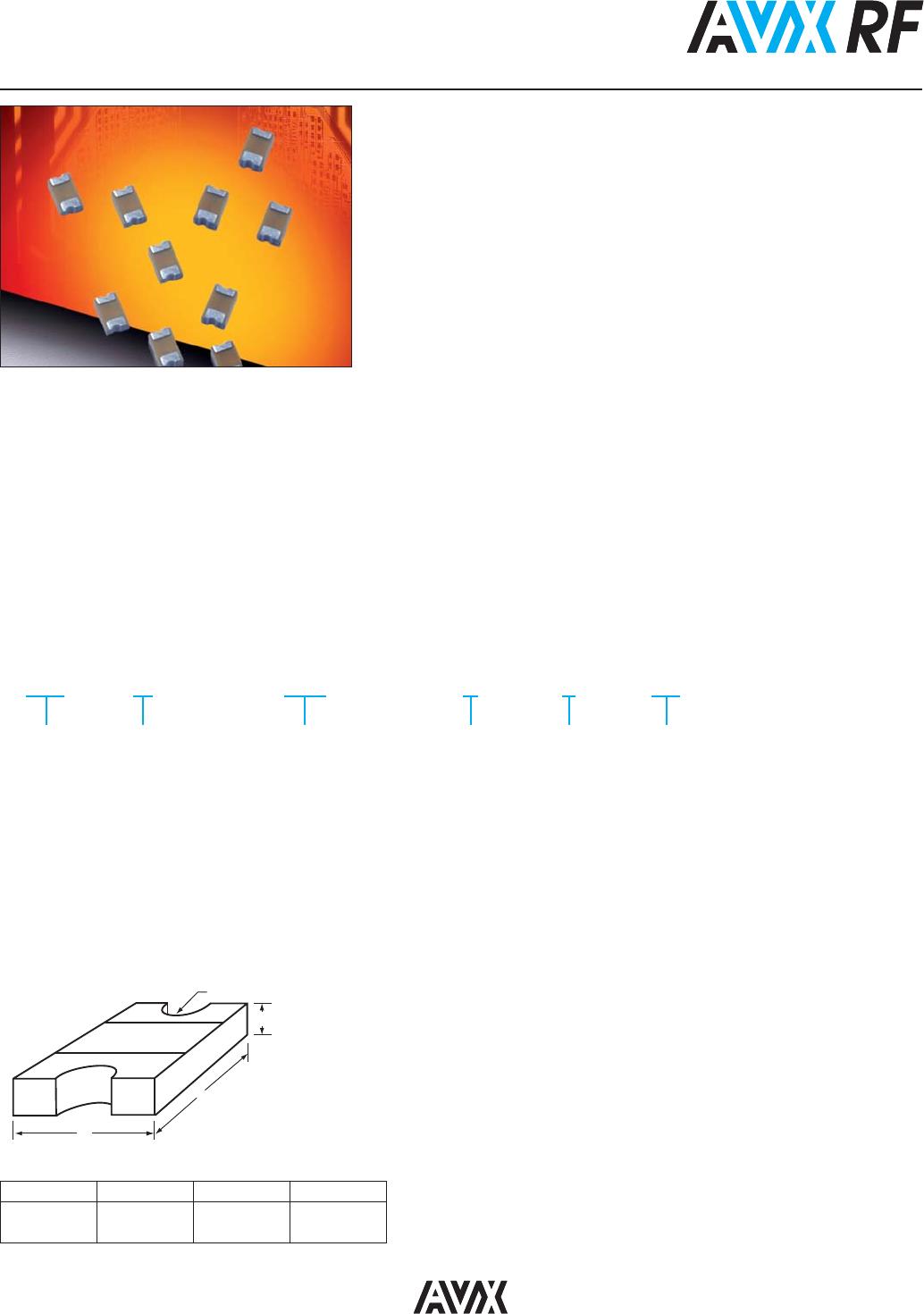
MLO
TM
Hi-Q Inductors
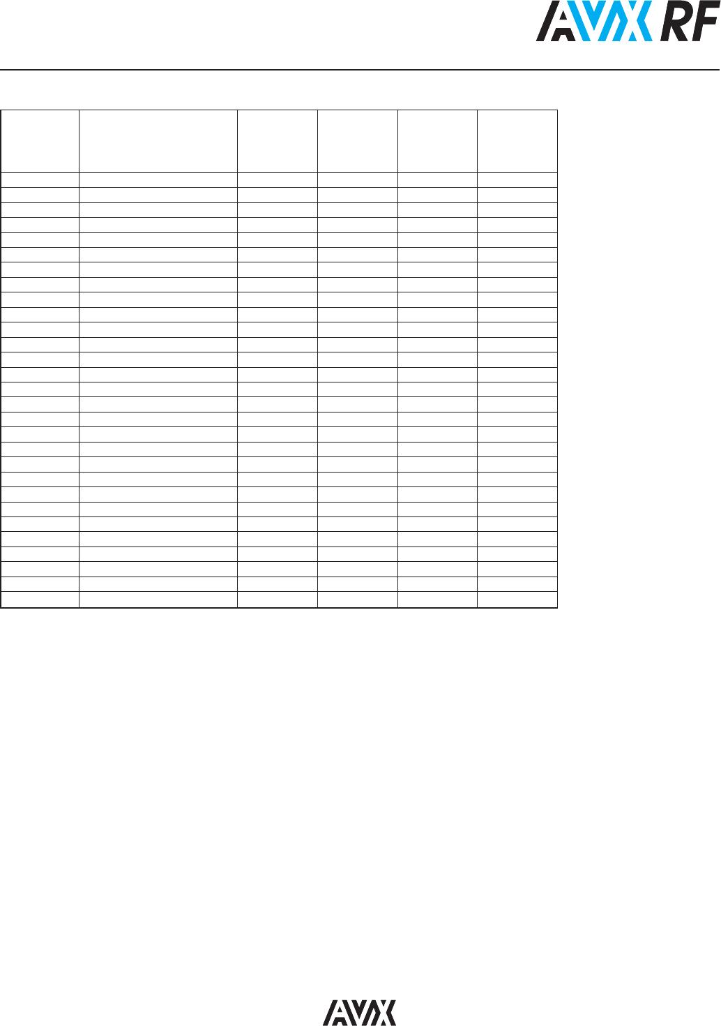
0402 ELECTRICAL SPECIFICATIONS
Available
L (nH) Inductance Tolerance Q min SRF min Rdc max Idc max
450MHz B = ±0.1nH, C = ±0.2nH 450MHz (GHz) (mΩ) (mA)
H = ±3%
0.8 ±0.1nH, ±0.2nH 17 7 100 350
0.9 ±0.1nH, ±0.2nH 17 7 100 350
1 ±0.1nH, ±0.2nH 17 7 100 330
1.1 ±0.1nH, ±0.2nH 17 7 100 330
1.2 ±0.1nH, ±0.2nH 17 7 110 330
1.3 ±0.1nH, ±0.2nH 17 7 130 330
1.5 ±0.1nH, ±0.2nH 17 7 150 330
1.6 ±0.1nH, ±0.2nH 17 7 150 300
1.8 ±0.1nH, ±0.2nH 17 7 160 300
2 ±0.1nH, ±0.2nH 17 7 180 245
2.2 ±0.1nH, ±0.2nH 17 7 200 245
2.4 ±0.1nH, ±0.2nH 17 7 200 245
2.7 ±0.1nH, ±0.2nH 17 7 250 245
3 ±0.1nH, ±0.2nH 17 7 300 225
3.3 ±0.1nH, ±0.2nH 17 7 340 225
3.6 ±0.1nH, ±0.2nH 17 7 350 200
3.9 ±0.1nH, ±0.2nH 17 7 400 200
4.7 ±0.1nH, ±0.2nH 17 7 480 195
5.6 ±0.1nH, ±0.2nH 17 7 500 170
6.8 ±3% 17 7 600 160
8.2 ±3% 17 6 800 130
10 ±3% 17 5 1000 120
12 ±3% 17 4 1100 110
15 ±3% 17 4 1200 110
18 ±3% 17 3 1500 110
22 ±3% 17 3 1900 95
27 ±3% 17 3 2100 95
30 ±3% 17 2 2200 85
32 ±3% 17 2 2200 85
Specifications based on performance of component assembled properly on printed circuit board with 50Ω nominal impedance.
Idc max: Maximum 15ºC rise in component temperature over ambient.