Automotive LED Array Driver
A6269
7
Allegro MicroSystems, LLC
115 Northeast Cutoff
Worcester, Massachusetts 01615-0036 U.S.A.
1.508.853.5000; www.allegromicro.com
Temperature Monitor A temperature monitor function,
included in the A6269, reduces the LED current as the silicon
junction temperature of the A6269 increases (see figure 2). By
mounting the A6269 on the same thermal substrate as the LEDs,
this feature can also be used to limit the dissipation of the LEDs.
As the junction temperature of the A6269 increases, the regulated
current level is reduced, reducing the dissipated power in the
A6269 and in the LEDs. The current is reduced from the 100%
level at typically 4% per degree Celsius until the point at which
the current drops to 25% of the full value, defined at T
JL
. Above
this temperature the current will continue to reduce at a lower
rate until the temperature reaches the overtemperature shutdown
threshold temperature, T
JF
.
The temperature at which the current reduction begins can be
adjusted by changing the voltage on the THTH pin. When THTH
is left open the temperature at which the current reduction begins
is defined as the thermal monitor activation temperature, T
JM
, and
is specified, in the characteristics table, at the 90% current level.
T
JM
will increase as the voltage at the THTH pin, V
THTH
, is
reduced and is defined as approximately:
0.0039
=
T
JM
(°C)
1.46 –V
THTH
(3)
A resistor connected between THTH and GND will reduce V
THTII
and increase T
JM
. A resistor connected between THTH and a refer-
ence supply greater than 1 V will increase V
THTH
and reduce T
JM
.
Figure 3 shows how the nominal value of the thermal monitor
activation temperature varies with the voltage at THTH and with
either a pull-down resistor, R
TH
, to GND or with a pull-up resis-
tor, R
TH
, to 3 V and to 5 V.
In extreme cases, if the chip temperature exceeds the overtem-
perature limit, T
JF
, all regulators will be disabled. The tempera-
ture will continue to be monitored and the regulators re-activated
when the temperature drops below the threshold provided by the
specified hysteresis.
Note that it is possible for the A6269 to transition rapidly
between thermal shutdown and normal operation. This can hap-
pen if the thermal mass attached to the exposed thermal pad is
small and T
JM
is increased to close to the shutdown temperature.
The period of oscillation will depend on T
JM
, the dissipated
power, the thermal mass of any heatsink present, and the ambient
temperature.
100
80
60
40
20
0
T
JM
T
JL
T
JF
90
25
70 90 110
Junction Temperature, T
J
(°C)
Relative Sense Current (%)
130 150 170
Figure 2. Temperature monitor current reduction.
250
200
150
100
50
0
1.3
1.2
1.1
1.0
0.9
0.8
V
THTH
70 80 90 110100
Thermal Monitor Activation Temperature, T
JM
(°C)
R
TH
(k)
V
THTH
(V)
130120 150140
R
TH
pull-up
to 5 V
R
TH
pull-up
to 3 V
R
TH
pull-down
to GND
Figure 3. T
JM
versus a pull-up or pull-down resistor, R
TH
, and V
THTH
.
Automotive LED Array Driver
A6269
8
Allegro MicroSystems, LLC
115 Northeast Cutoff
Worcester, Massachusetts 01615-0036 U.S.A.
1.508.853.5000; www.allegromicro.com
Application Information
Power Dissipation
The most critical design considerations when using a linear regu-
lator such as the A6269 are the power produced internally as heat
and the rate at which that heat can be dissipated.
There are three sources of power dissipation in the A6269:
• The quiescent power to run the control circuits
• The power in the reference circuit
• The power due to the regulator voltage drop
The elements relating to these dissipation sources are illustrated
in figure 4.
Quiescent Power The quiescent power is the product of the
quiescent current, I
INQ
, and the supply voltage, V
IN
, and is not
related to the regulated current. The quiescent power, P
Q
, is there-
fore defined as:
P
Q
= V
IN
× I
INQ
(4)
Reference Power The reference circuit draws the reference
current from the supply and passes it through the reference resis-
tor to ground. The reference current is 8% of the output current
on any one active output. The reference circuit power is the prod-
uct of the reference current and the difference between the supply
voltage and the reference voltage, typically 1.2 V. The reference
power, P
REF
, is therefore defined as:
P
REF
=
R
REF
(V
IN
V
REF
) × V
REF
(5)
Regulator Power In most application circuits the largest dis-
sipation will be produced by the output current regulators. The
power dissipated in each current regulator is simply the product
of the output current and the voltage drop across the regulator.
The total current regulator dissipation is the sum of the dissipa-
tion in each output regulator. The regulator power for each output
is defined as:
P
REGx
=
(V
IN
V
LEDx
) × I
LEDx
(6)
where x is 1 or 2.
Note that the voltage drop across the regulator, V
REG
, is always
greater than the specified minimum drop-out voltage, V
DO
. The
output current is regulated by making this voltage large enough
to provide the voltage drop from the supply voltage to the total
forward voltage of all LEDs in series, V
LED
.
The total power dissipated in the A6269 is the sum of the qui-
escent power, the reference power, and the power in each of the
regulators:
P
DIS
=
P
Q
+ P
REF
+ P
REGA
+ P
REGB
+ P
REGC
+ P
REGD
(7)
The power that is dissipated in each string of LEDs is:
P
LEDx
=
V
LEDx
× I
LEDx
(8)
where x is A, B, C, or D, and V
LEDx
is the voltage across all
LEDs in the string.
Figure 4. Internal power dissipation sources.
A6269
LAx
I
LAx
I
INQ
I
REF
VIN
GND
IREF
R
REF
V
REF
V
LED
V
REG
V
IN
Automotive LED Array Driver
A6269
9
Allegro MicroSystems, LLC
115 Northeast Cutoff
Worcester, Massachusetts 01615-0036 U.S.A.
1.508.853.5000; www.allegromicro.com
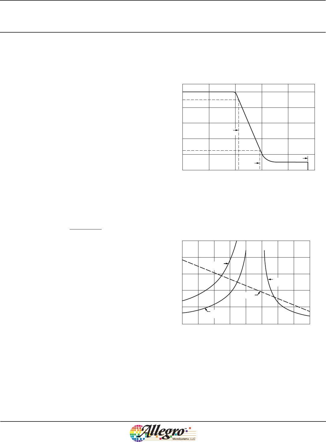
From these equations (and as illustrated in figure 5) it can be seen
that, if the power in the A6269 is not limited, then it will increase
as the supply voltage increases but the power in the LEDs will
remain constant.
Dissipation Limits
There are two features limiting the power that can be dissipated
by the A6269: thermal shutdown and thermal foldback.
Thermal Shutdown If the thermal foldback feature is disabled
by connecting the THTH pin to GND, or if the thermal resistance
from the A6269 to the ambient environment is high, then the
silicon temperature will rise to the thermal shutdown threshold
and the current will be disabled. After the current is disabled the
power dissipated will drop and the temperature will fall. When
the temperature falls by the hysteresis of the thermal shutdown
circuit, then the current will be re-enabled and the temperature
will start to rise again. This cycle will repeat continuously until
the ambient temperature drops or the A6269 is switched off. The
period of this thermal shutdown cycle will depend on several
electrical, mechanical, and thermal parameters, and could be from
a few milliseconds to a few seconds.
Thermal Foldback If there is a good thermal connection to the
A6269, then the thermal foldback feature will have time to act.
This will limit the silicon temperature by reducing the regulated
current and therefore the dissipation.
The thermal monitor will reduce the LED current as the tempera-
ture of the A6269 increases above the thermal monitor activation
temperature, T
JM
, as shown in figure 6. The figure shows the
operation of the A6269 with 2 strings of 3 red LEDs, each string
running at 100 mA. The forward voltage of each LED is 2.3 V and
the graph shows the current as the supply voltage increases from
14 to 17 V. As the supply voltage increases, without the thermal
foldback feature, the current would remain at 100 mA, as shown
by the dashed line. The solid line shows the resulting current
decrease as the thermal foldback feature acts.
If the thermal foldback feature did not affect LED current, the
current would increase the power dissipation and therefore the
silicon temperature. The thermal foldback feature reduces power
in the A6269 in order to limit the temperature increase, as shown
in figure 7. The figure shows the operation of the A6269 under
the same conditions as figure 6. That is, 2 strings of 3 red LEDs,
each string running at 100 mA with each LED forward voltage
Figure 5. Power Dissipation versus Supply Voltage
3.0
2.5
2.0
1.5
1.0
0.5
0
A6269 Power
Supply Voltage, V
IN
(V)
Power Dissipation, P
D
(W)
LED Power
2 Strings
V
LED
= 6.9 V
I
LED
= 100 mA
89 1110 1312 161514
Figure 6. LED current versus Supply Voltage
Figure 7. Junction Temperature versus Supply Voltage
54
52
50
48
46
44
42
40
Without thermal monitor
With thermal monitor
14.0 14.5 15.0 16.0 17.015.5
Supply Voltage, V
IN
(V)
I
LED
(mA)
16.5
2 Strings
V
LED
= 6.9 V
I
LED
= 100 mA
T
A
= 50°C
130
125
120
115
110
105
100
Without thermal monitor
With thermal monitor
14.0 14.5 15.0 16.0 17.015.5
Supply Voltage, V
IN
(V)
T
J
(°C)
16.5
2 Strings
V
LED
= 6.9 V
I
LED
= 100 mA
T
A
= 50°C

A6269KLJTR-T

Mfr. #:
Manufacturer:
Description:
IC LED DRVR LIN DIM 200MA 8SOIC
Lifecycle:
New from this manufacturer.
Delivery:
DHL FedEx Ups TNT EMS
Payment:
T/T Paypal Visa MoneyGram Western Union

Products related to this Datasheet