I
NTEGRATED
C
IRCUITS
D
IVISION
CPC1025N
400V Normally-Open Single-Pole
4-Pin SOP OptoMOS
®
Relay
www.ixysic.com
DS-CPC1025N-R08
1
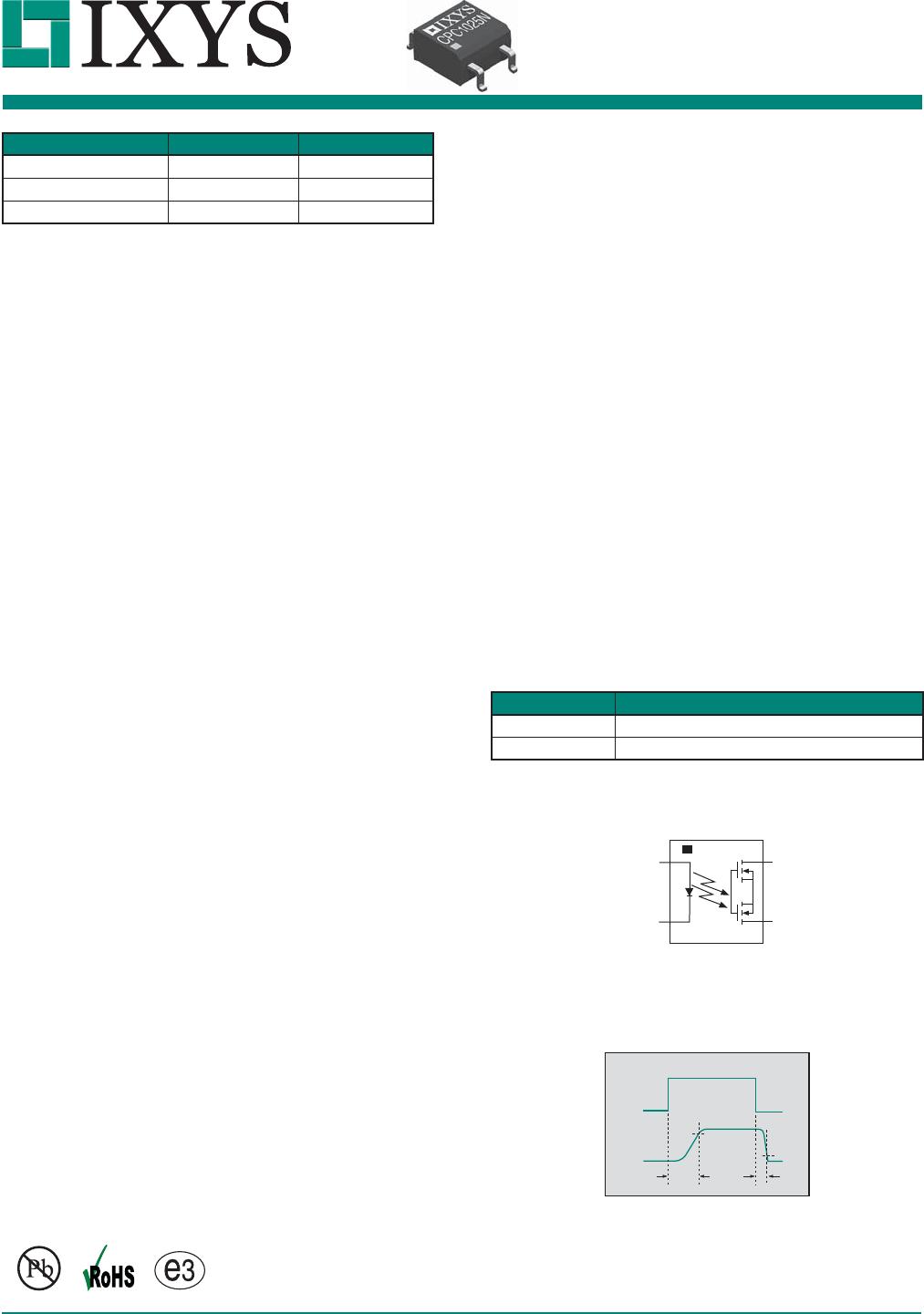
Part # Description
CPC1025N 4-Pin SOP (100/tube)
CPC1025NTR 4-Pin SOP (2000/reel)
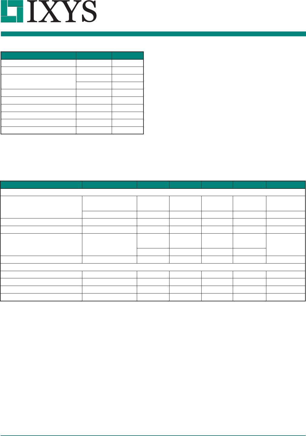
Parameter Rating Units
Blocking Voltage 400 V
P
Load Current 120 mA
rms
/ mA
DC
On-Resistance (max) 30
Applications
Features
Description
Ordering Information
Pin Configuration
• Telecommunications
• Telecom Switching
• Tip/Ring Circuits
• Modem Switching (Laptop, Notebook, Pocket
Size)
• Hook Switch
• Dial Pulsing
• Ground Start
• Ringing Injection
• Instrumentation
• Multiplexers
• Data Acquisition
• Electronic Switching
• I/O Subsystems
• Meters (Watt-Hour, Water, Gas)
• Medical Equipment—Patient/Equipment Isolation
• Security
• Aerospace
• Industrial Controls
• 1500V
rms
Input/Output Isolation
• Small 4-Pin SOP Package
• Low Drive Power Requirements
• High Reliability
• Arc-Free With No Snubbing Circuits
• No EMI/RFI Generation
• Wave Solderable
• Tape & Reel Version Available
The CPC1025N is a miniature normally-open
(1-Form-A) solid state relay in a 4-pin SOP package
that employs optically coupled MOSFET technology
to provide 1500V
rms
of input to output isolation. The
efficient MOSFET switches and photovoltaic die
use IXYS Integrated Circuits Division’s patented
OptoMOS architecture while the optically coupled
output is controlled by a highly efficient infrared LED.
The CPC1025N uses IXYS Integrated Circuits
Division’s state of the art double-molded vertical
construction packaging to produce one of the world’s
smallest relays. It offers board space savings of at
least 20% over the competitor’s larger 4-pin SOP
relay.
Approvals
Switching Characteristics
of Normally-Open Devices
Form-A
I
F
I
LOAD
10%
90%
t
on
t
off
1
2
3
4
+ Control
– Control
Load
Load
• UL Recognized Component: File E76270
• CSA Certified Component: Certificate 1172007
• EN/IEC 60950-1 Certified Component:
Certificate B 13 12 82667 003