PLTT0805Z1621QGT5

PLTT
www.vishay.com
Vishay Dale Thin Film
Revision: 08-Jul-16
1
Document Number: 60082
For technical questions, contact: thinfilm@vishay.com
THIS DOCUMENT IS SUBJECT TO CHANGE WITHOUT NOTICE. THE PRODUCTS DESCRIBED HEREIN AND THIS DOCUMENT
ARE SUBJECT TO SPECIFIC DISCLAIMERS, SET FORTH AT www.vishay.com/doc?91000
Precision Low TCR High Temperature Thin Film Resistor,
Surface Mount Chip, ± 5 ppm/°C TCR, 0.02 % Tolerance
Vishay’s proven precision thin film wraparound resistors will
meet your exact requirements. These resistors are ideal for
use in oil industry precision applications requiring low noise,
long term stability under high temperature, ultra low
temperature coefficient of resistance, and low voltage
coefficient. The chip resistors are available in any resistance
ohmic value in the range specified below.
CONSTRUCTION
FEATURES
PLTT0603 case size is qualified to AEC-Q200
for automotive applications
-55 °C to 215 °C operating temperature range
TCR of ± 5 ppm/°C standard
Tolerances to ± 0.02 %
Anti corrosion resistant film with (SPM) special
passivation method
Stable film and performance characteristics
0.5 % max. at 2000 h, 215 °C, 25 % rated power
Non-standard resistance values available
Very low noise and voltage coefficient
(< -30 dB, 0.1 ppm/V)
UL 94 V-0 flame resistant
Gold terminations (10 μ" to 20 μ")
Material categorization: for definitions of compliance
please see www.vishay.com/doc?99912
TYPICAL PERFORMANCE
Note
Consult factory for additional case size
Adhesion Layer
High Purity
Alumina Substrate
Nickel Barrier
Plated
Gold (10 μ" to 20 μ")
SPM Passivation
Enhancement
Passivated Nichrome
Resistive Film
ABSOLUTE
TCR 5
TOL. 0.02
Available
Available
STANDARD ELECTRICAL SPECIFICATIONS
TEST SPECIFICATIONS CONDITIONS
Material Passivated nichrome -
Resistance Range 50 to 3 M -
TCR: Absolute ± 5 ppm/°C -55 °C to +215 °C
Tolerance: Absolute ± 0.1 % to ± 0.02 % +25 °C
Stability: Absolute R ± 0.5 % 2000 h at 215 °C, 25 % rated power
Stability: Ratio --
Voltage Coefficient ± 0.1 ppm/V (typical) -
Working Voltage 100 V to 200 V -
Operating Temperature Range -55 °C to +215 °C -
Storage Temperature Range -55 °C to +215 °C -
Noise < - 35 dB (typical) -
Shelf Life Stability: Absolute R ± 0.01 % 1 year at +25 °C
COMPONENT RATINGS
CASE SIZE
POWER RATING
AT 70 °C
(mW)
WORKING VOLTAGE
(V)
RESISTANCE RANGE
()
0603 150 75 75 to 130K
0805 250 100 250 to 260K
1206 400 200 500 to 775K
2010 800 200 500 to 2M
2512 1000 200 500 to 3M
PLTT
www.vishay.com
Vishay Dale Thin Film
Revision: 08-Jul-16
2
Document Number: 60082
For technical questions, contact: thinfilm@vishay.com
THIS DOCUMENT IS SUBJECT TO CHANGE WITHOUT NOTICE. THE PRODUCTS DESCRIBED HEREIN AND THIS DOCUMENT
ARE SUBJECT TO SPECIFIC DISCLAIMERS, SET FORTH AT www.vishay.com/doc?91000
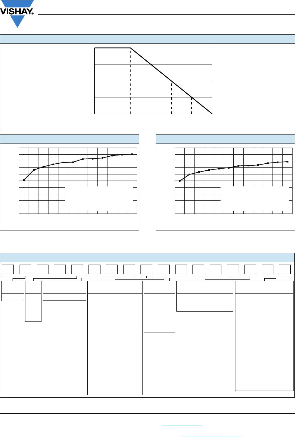
DIMENSIONS in inches
CASE SIZE TERM L W T D E
0603 G 0.064 ± 0.006 0.032 ± 0.005 0.015 to 0.033 0.012 ± 0.005 0.015 ± 0.005
0805 G 0.080 ± 0.006 0.050 ± 0.005 0.015 to 0.033 0.016 ± 0.008 0.015 ± 0.005
1206 G 0.126 ± 0.008 0.063 ± 0.005 0.015 to 0.033 0.020 + 0.005/- 0.010 0.020 + 0.005/- 0.010
2010 G 0.209 ± 0.009 0.098 ± 0.005 0.015 to 0.033 0.020 ± 0.005 0.020 ± 0.005
2512 G 0.259 ± 0.009 0.124 ± 0.005 0.015 to 0.033 0.020 ± 0.005 0.020 ± 0.005
ENVIRONMENTAL TESTS - MIL-PRF-55342
ENVIRONMENTAL TEST CONDITIONS
TYPICAL VISHAY
PERFORMANCE
Thermal Shock MIL-STD-202 method 107 Cond F, -65 °C to +150 °C ± 0.02 %
Short Time Overload MIL-PRF-55342 Para 4.8.6, 2.5x rated working voltage ± 0.01 %
Low Temperature Operation MIL-PRF-55342 Para 4.8.5, -65 °C ± 0.01 %
Resistance to Soldering Heat MIL-STD-202 method 210 ± 0.01 %
Moisture Resistance MIL-STD-202 method 106, no power applied ± 0.02 %
High Temperature Exposure MIL-PRF-55342 Para 4.8.7, at 150 °C for 100 h ± 0.02 %
Life
MIL-STD-202 method 108, 25 % rated power
for 2000 h at 215 °C
± 0.50 %
TCR MIL-STD-202 method 304 ± 5 ppm/°C
ENVIRONMENTAL TESTS - AEC-Q200 PLTT0603 Case Size Only
ENVIRONMENTAL TEST CONDITIONS
TYPICAL VISHAY
PERFORMANCE
High temperature storage MIL-STD-202 method 108, 1000 h at 125 °C ± 0.10 %
Temperature cycling
JESD22 method JA-104, 1000 cycles,
-55 °C to +155 °C
± 0.25 %
Moisture resistance MIL-STD-202 method 106, no power applied ± 0.10 %
Biased humidity
MIL-STD-202 method 103, 1000 h at 85 °C,
85 % RH, 10 % rated power
± 0.20 %
Life
MIL-STD-202 method 108,
1000 h at 175 °C, 50 % rated power
± 0.50 %
Mechanical shock MIL-STD-202 method 213, condition C ± 0.02 %
Vibration MIL-STD-202 method 204, 10 Hz to 2 kHz ± 0.02 %
Resistance to soldering heat MIL-STD-202 method 210, condition B ± 0.02 %
Electrostatic discharge AEC-Q200-002, human body (< 1 k: 1 kV; > 1 k: 2 kV) < 1 k: 1 kV; > 1 k: 2 kV
Solderability MIL-STD-883 method 2003 para 2.3.1 and J-STD-002 Pass
TCR MIL-STD-202 method 304 ± 5 ppm /°C
Die shear MIL-PRF-55342, 0.5 kg for 30 s minimun Pass
Flame retardance AEC-Q200-001 para 4.0 Pass
D
W
L
T
E
PLTT
www.vishay.com
Vishay Dale Thin Film
Revision: 08-Jul-16
3
Document Number: 60082
For technical questions, contact: thinfilm@vishay.com
THIS DOCUMENT IS SUBJECT TO CHANGE WITHOUT NOTICE. THE PRODUCTS DESCRIBED HEREIN AND THIS DOCUMENT
ARE SUBJECT TO SPECIFIC DISCLAIMERS, SET FORTH AT www.vishay.com/doc?91000
Note
Performance obtained with following mounting conditions
PCB: Polymide IPC-7831A STD land patterns
Solder paste: PbSnAg (93.5/5/1.5)
Note
(1)
Q tolerances are available only for resistance values 250 .
DERATING CURVE
Ambient Temperature °C
070 215230
Percent of Rated Power
0
25
50
75
100
175
PLTT0805 500 STABILITY TEST RESULTS
Time on Test (h)
Maximum Δ (%)
- 0.50
- 0.30
- 0.10
0.10
0.30
0.50
0.00
0.20
0.40
- 0.20
- 0.40
425 1525125011001000750 2000500 17752501250
Test Conditions:
Case Size: 0805
Resistance Value: 500 Ω
Applied Power: 25 % of rated power
Test Chamber Temperature: 215 °C
PLTT0805 50 k STABILITY TEST RESULTS
Time on Test (h)
Maximum Δ (%)
- 0.50
- 0.30
- 0.10
0.10
0.30
0.50
0.00
0.20
0.40
- 0.20
- 0.40
425 1525125011001000750 2000500 17752501250
Test Conditions:
Case Size: 0805
Resistance Value: 50 kΩ
Applied Power: 25 % of rated power
Test Chamber Temperature: 215 °C
GLOBAL PART NUMBER INFORMATION
GLOBAL
MODEL
CASE
SIZE
TCR
CHARACTERISTIC
RESISTANCE TOLERANCE TERMINATION PACKAGING
PLTT 0603
0805
1206
2010
2512
Z = ± 5 ppm/°C The first 3 digits are
significant figures and
the last digit specifies
the number of zeros to
follow. “R” designates
the decimal point.
Example:
1001 = 1 k
2500 = 250 
Special values with more
than 4 significant figures,
use a R for value below
1 k and a K for values
greater than 1 k to
signify a decimal point.
982R6 = 982.6 
532R41 = 532.41
Q =
± 0.02 %
(1)
A = ± 0.05 %
B = ± 0.1 %
D = ± 0.5 %
F = ± 1 %
G = ± 2 %
G = Wraparound Gold
over Ni barrier
(10 μ" min. Au)
WS = WAFFLE
WI = 100 min./1mult
(item single lot date code)
WP = 100 min./1mult
(package unit single lot
date code)
TAPE AND REEL
T0 = 100 min., 100 mult
T1 = 1000 min., 1000 mult
T5 = 500 min., 500 mult
TF = Full reel
TS = 100 min., 1 mult
TI = 100 min./1mult
(item single lot date code)
TP = 100 min., 1 mult
(package unit single lot
date code)
05Z1 01Q00 GT1TPL 8
T

PLTT0805Z1621QGT5

Mfr. #:
Manufacturer:
Vishay
Description:
Thin Film Resistors - SMD 1/4W 1.62KOhms 0.02% 5PPM 0805
Lifecycle:
New from this manufacturer.
Delivery:
DHL FedEx Ups TNT EMS
Payment:
T/T Paypal Visa MoneyGram Western Union