MAX16000–MAX16007
Low-Voltage, Quad-/Hex-/Octal-Voltage
µP Supervisors
7
Maxim Integrated
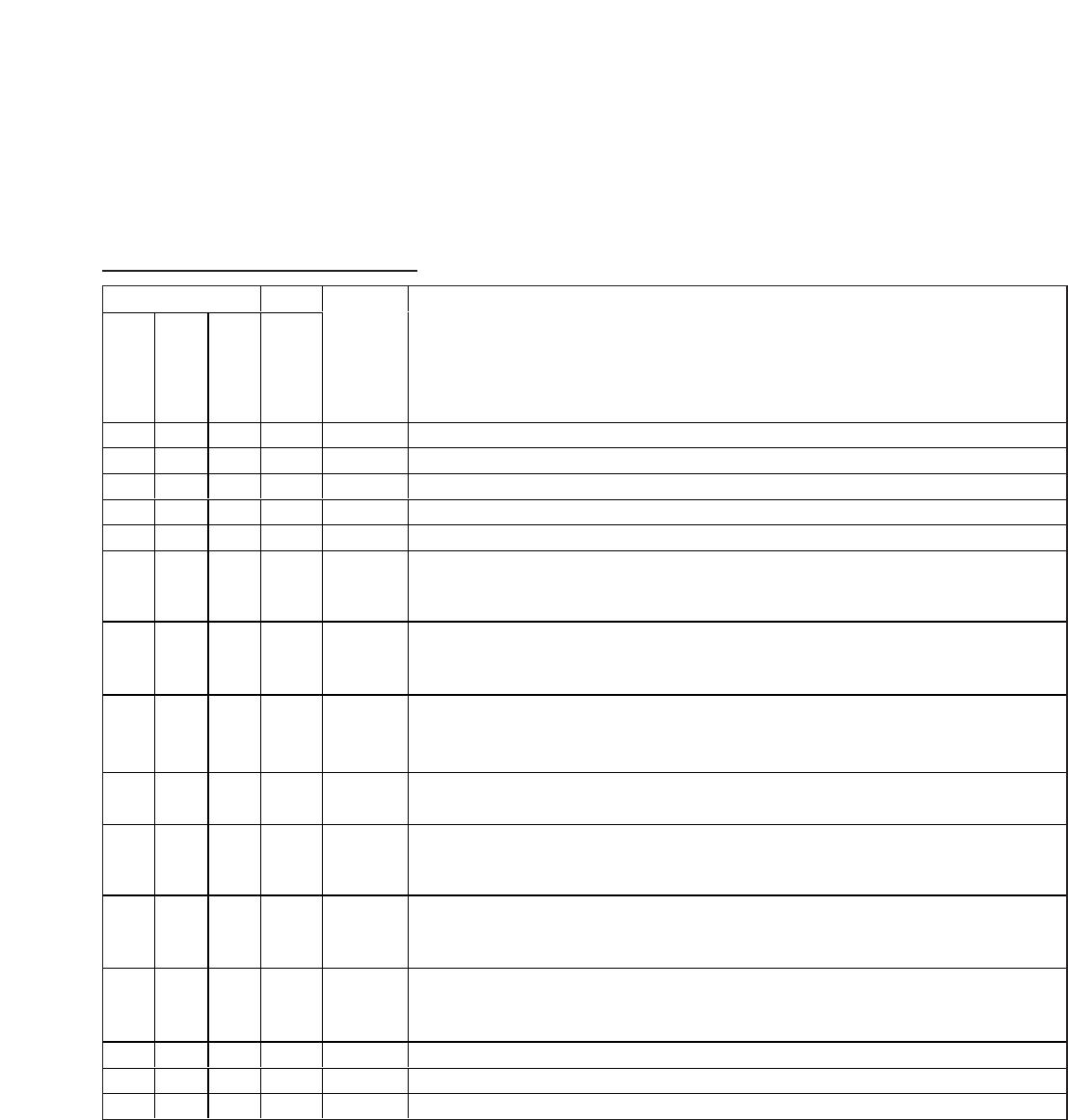
Pin Description (MAX16000/MAX16001/MAX16002)
PIN
MAX16000
MAX16001
MAX16002
NAME FUNCTION
1 1 1 IN3 Monitored Input Voltage 3. See Table 1 for the input voltage threshold.
2 2 2 IN4 Monitored Input Voltage 4. See Table 1 for the input voltage threshold.
3 4 4 GND Ground
455 V
CC
Unmonitored Power-Supply Input
5 6 — OUT3
O utp ut 3. When the vol tag e at IN 3 fal l s b el ow i ts thr eshol d , OU T3 g oes l ow and stays l ow unti l the
vol tag e at IN 3 exceed s i ts thr eshol d . The op en- d r ai n outp ut has a 30µA i nter nal p ul l up to V
C C
.
6 7 — OUT4
O utp ut 4. When the vol tag e at IN 4 fal l s b el ow i ts thr eshol d , OU T4 g oes l ow and stays l ow unti l the
vol tag e at IN 4 exceed s i ts thr eshol d . The op en- d r ai n outp ut has a 30µA i nter nal p ul l up to V
C C
.
7108 MARGIN
Active-Low Manual Deassert Input. Pull MARGIN low to deassert all outputs (go into high state),
regardless of the voltage at any monitored input.
8 11 — OUT2
O utp ut 2. When the vol tag e at IN 2 fal l s b el ow i ts thr eshol d , OU T2 g oes l ow and stays l ow unti l the
vol tag e at IN 2 exceed s i ts thr eshol d . The op en- d r ai n outp ut has a 30µA i nter nal p ul l up to V
C C
.
9 12 — OUT1
O utp ut 1. When the vol tag e at IN 1 fal l s b el ow i ts thr eshol d , OU T1 g oes l ow and stays l ow unti l the
vol tag e at IN 1 exceed s i ts thr eshol d . The op en- d r ai n outp ut has a 30µA i nter nal p ul l up to V
C C
.
10 14 10 IN1 Monitored Input Voltage 1. See Table 1 for the input voltage threshold.
11 15 11 IN2 Monitored Input Voltage 2. See Table 1 for the input voltage threshold.
12 16 12 TOL
Threshold Tolerance Input. Connect TOL to GND to select 5% threshold tolerance. Connect TOL
to V
CC
to select 10% threshold tolerance.
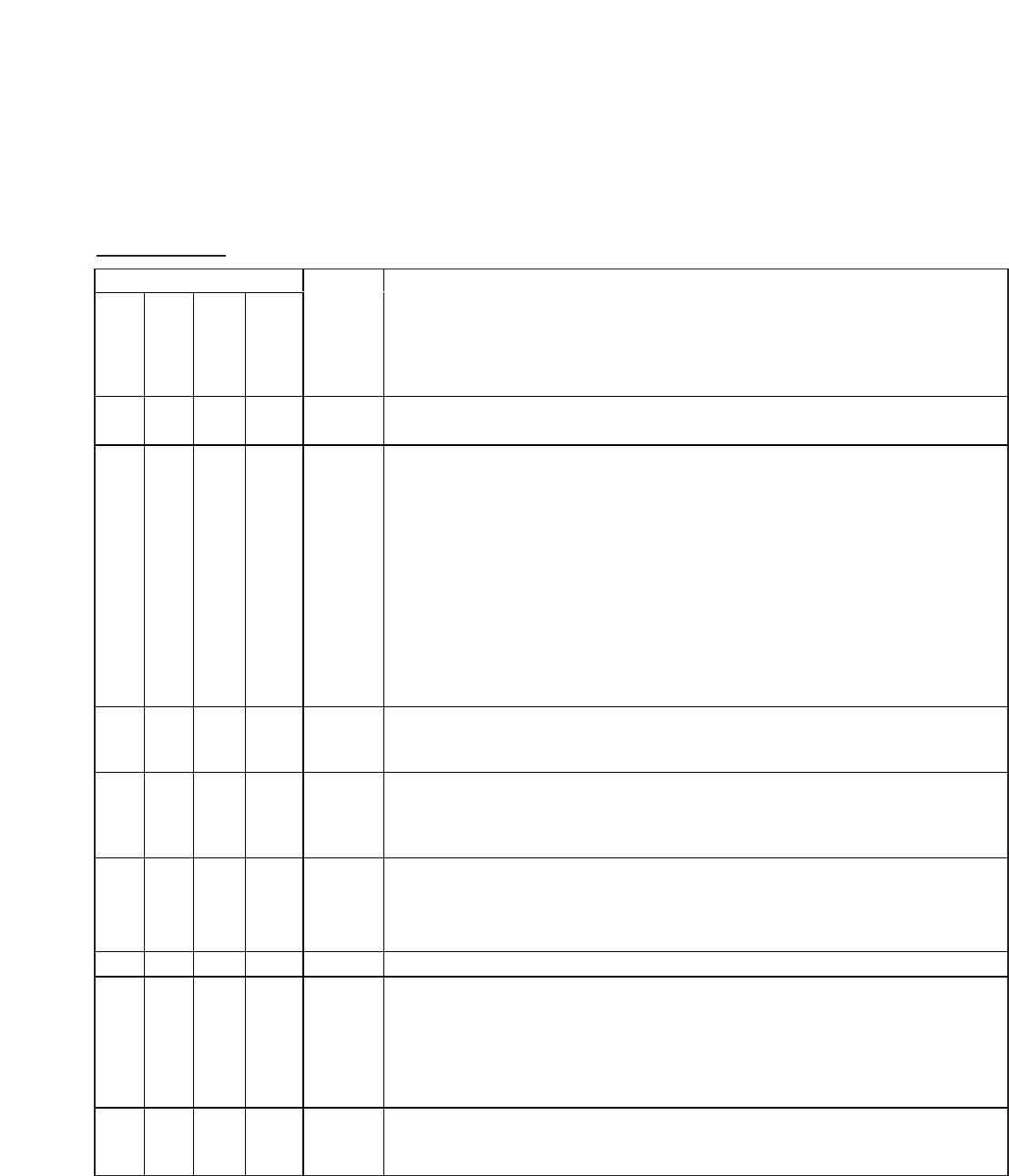
— 3 3 WDI
Watchdog Timer Input. If WDI remains low or high for longer than the watchdog timeout period,
RESET is asserted. The timer clears whenever a reset is asserted or a rising or falling edge on
WDI is detected. The watchdog timer enters a startup period that allows 54s for the first
transition to occur before a reset. Leave WDI unconnected to disable the watchdog timer. The
WDI open-state detector uses a small 400nA current. Therefore, do not connect WDI to anything
that will source or sink more than 200nA. Note that the leakage current specification for most
three-state drivers exceeds 200nA.
—8 6 MR
Active-Low Manual Reset Input. Pull MR low to assert RESET low. RESET remains low for the
reset timeout period after MR is deasserted. MR is pulled up to V
CC
through a 20kΩ resistor.
— 9 7 SRT
Set Reset Timeout Input. Connect a capacitor from SRT to GND to set the reset timeout period.
The reset timeout period can be calculated as follows:
Reset Timeout (s) = 2.06 x 10
6
(Ω) x C
SRT
(F). For the internal timeout period of 140ms (min),
connect SRT to V
CC
.
—13 9 RESET
Active-Low Reset Output. RESET asserts low when any of the monitored voltages falls below its
respective threshold or MR is asserted. RESET remains asserted for the reset timeout period
after all monitored voltages exceed their respective thresholds and MR is deasserted. This
open-drain output has a 30µA internal pullup.
—— — EP
Exposed Pad. EP is internally connected to GND. Connect EP to the ground plane to provide a
low thermal resistance path from the IC junction to the PCB. Do not use as the electrical
connection to GND.