LTC6993-1/LTC6993-2
LTC6993-3/LTC6993-4
15
69931234fc
For more information www.linear.com/LTC6993-1
operaTion
Changing DIVCODE After Start-Up
Following start-up, the A/D converter will continue
monitoring V
DIV
for changes. Changes to DIVCODE will
be recognized slowly, as the LTC6993 places a priority on
eliminating any “wandering” in the DIVCODE. The typical
delay depends on the difference between the old and
new DIVCODE settings and is proportional to the master
oscillator period.
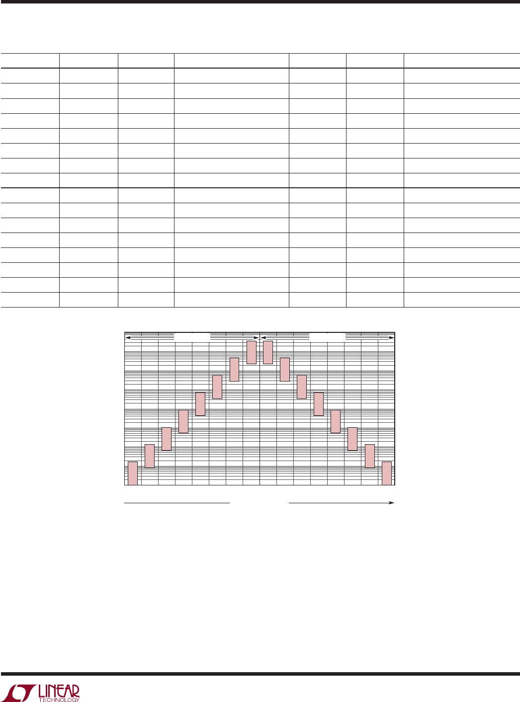
t
DIVCODE
= 16 • (∆DIVCODE + 6) • t
MASTER
A change in DIVCODE will not be recognized until it is
stable, and will not pass through intermediate codes. A
digital filter is used to guarantee the DIVCODE has settled
to a new value before making changes to the output. How
-
ever, if the output pulse is active during the transition, the
pulse width can take on a value between the two settings.
Start-Up Time
When power is first applied, the power
-on reset (POR)
circuit will initiate the start-up time, t
START
. The OUT pin
is held low during this time. The typical value for t
START
ranges from 0.5ms to 8ms depending on the master oscil-
lator frequency (independent of N
DIV
):
t
START(TYP)
= 500 • t
MASTER
During start-up, the DIV pin A/D converter must deter-
mine the correct DIVCODE before an output pulse can be
generated.
The
start-up time may increase if the supply
or DIV pin voltages are not stable. For this reason, it is
recommended to minimize the capacitance on the DIV
pin so it will properly track V
+
. Less than 100pF will not
extend the start-up time.
The DIVCODE setting is recognized at the end of the startup
up. If POL = 1, the output will transition high. Otherwise
(if POL = 0) OUT simply remains low. At this point, the
LTC6993 is ready to respond to rising/falling edges on
the TRIG input.
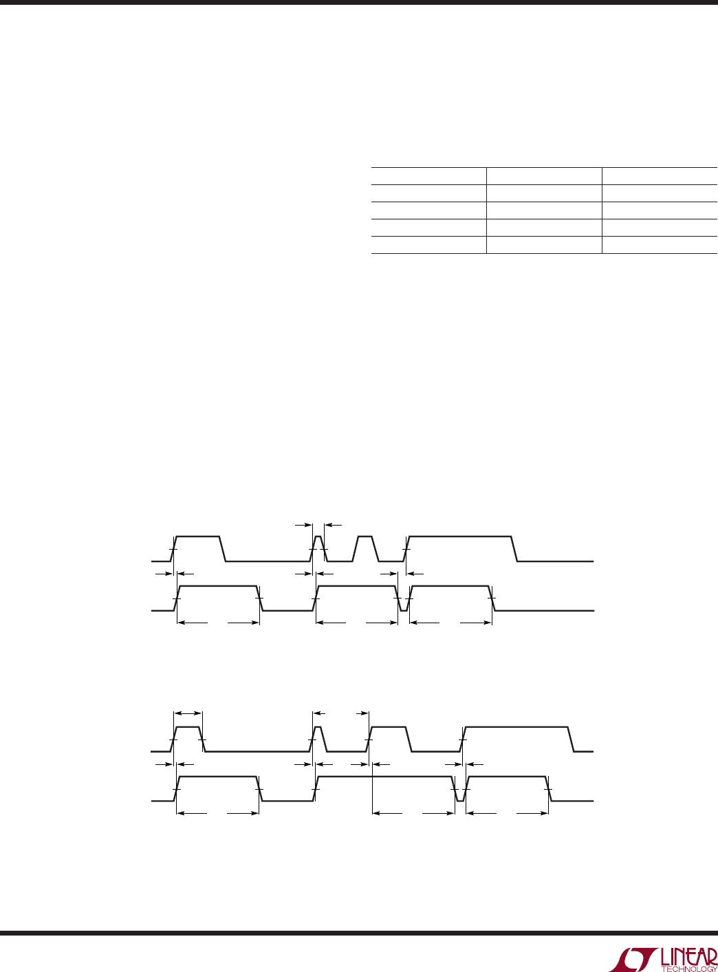
Figure 5a. DIVCODE Change from 0 to 2
Figure 5b. DIVCODE Change from 2 to 0
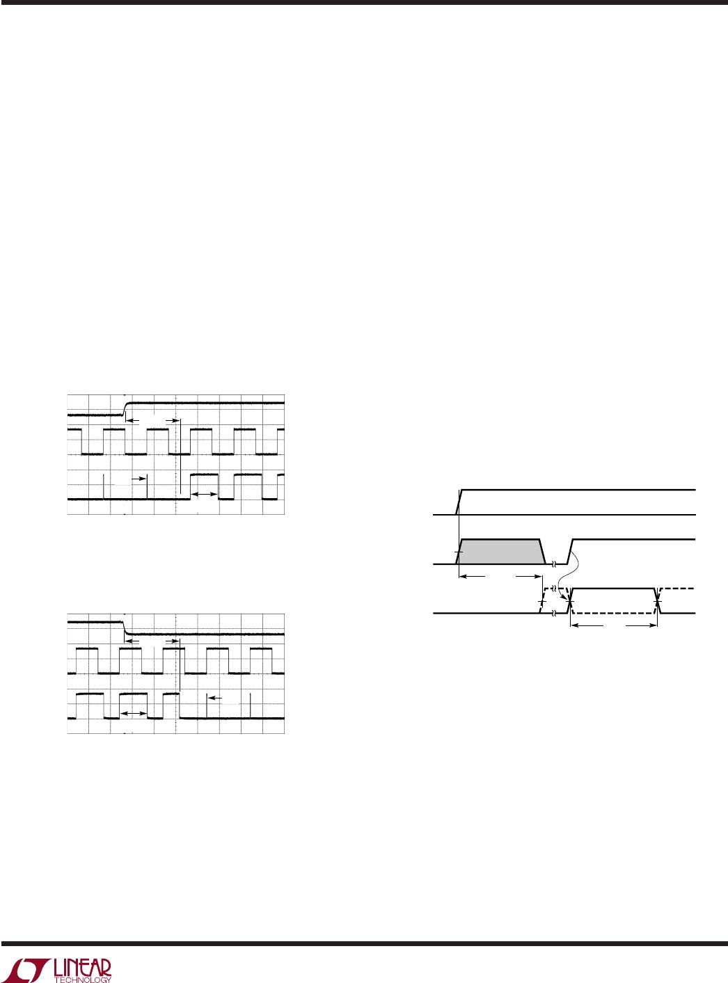
Figure 6. Start-Up Timing Diagram
500mV/DIV
TRIG
2V/DIV
OUT
2V/DIV
LTC6993-1
V
+
= 3.3V
R
SET
= 200k
200µs/DIV
69931234 F05a
512µs
256µs
4µs
DIV
500mV/DIV
TRIG
2V/DIV
OUT
2V/DIV
LTC6993-1
V
+
= 3.3V
R
SET
= 200k
200µs/DIV
69931234 F05b
512µs
256µs
4µs
TRIG
V
+
OUT
t
START
(TRIG IGNORED)
t
OUT
POL = 1
69931234 F06
POL = 0