(3/9)
20160708 / 3tf_commercial_yff-p_en.fm
Please be sure to request delivery specifications that provide further details on the features and specifications of the products for proper and safe use.
Please note that the contents may change without any prior notice due to reasons such as upgrading.
YFF-P series
YFF15PC type
SHAPE & DIMENSIONS RECOMMENDED LAND PATTERN
* Make sure to connect the GND terminal of this product and the GND of the mounting circuit board by using through holes so that the distance between
them is the shortest.
ELECTRICAL CHARACTERISTICS
CHARACTERISTICS SPECIFICATION TABLES
The part numbers are TDK’s standard specification products.
: Reel size code, 0 (ø178) or 9 (ø330).
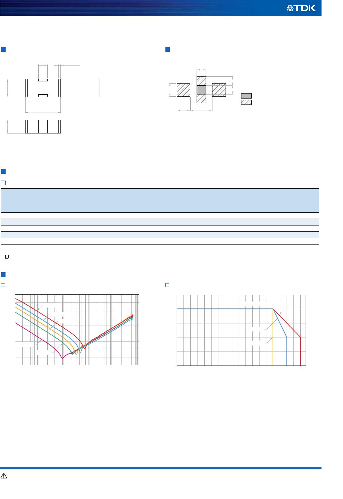
ELECTRICAL CHARACTERISTICS GRAPH
INSERTION LOSS vs. FREQUENCY CHARACTERISTICS
RATED CURRENT
vs.
TEMPERATURE CHARACTERISTICS (DERATING)
Part No. L (mm) W (mm) T (mm) B (mm) C (mm)
YFF15PC0G106MT00□N
1.00±0.20 0.50±0.20 0.50±0.15 0.07min. 0.35±0.10
YFF15PC0G755MT00□N
1.00±0.20 0.50±0.15 0.50±0.15 0.07min. 0.35±0.10
YFF15PC0G435MT00□N
1.05±0.05 0.65±0.05 0.45±0.05 0.09min. 0.30±0.10
YFF15PC0G105MT00□N
1.00±0.05 0.55±0.05 0.30±0.05 0.09min. 0.30±0.10
YFF15PC0J474MT00□N
1.00±0.05 0.55±0.05 0.30±0.05 0.09min. 0.30±0.10
YFF15PC1A224MT00□N
1.00±0.05 0.55±0.05 0.30±0.05 0.09min. 0.30±0.10
YFF15PC1C104MT00□N
1.00±0.05 0.55±0.05 0.30±0.05 0.09min. 0.30±0.10
Insertion loss
40dB frequency range
(MHz)
Rated voltage
Edc
(V)
Rated current
Idc
(A)
Operating
temperature range
(°C)
Storage temperature
range
(After mounting)
(°C)
Part No.
0.07 to 1000 4 2 –55 to 85 –55 to 85
YFF15PC0G106MT00 □ N
0.11 to 1000 4 2 –55 to 85 –55 to 85
YFF15PC0G755MT00 □ N
0.2 to 1000 4 2 –55 to 85 –55 to 85
YFF15PC0G435MT00 □ N
0.8 to 1000 4 3 –55 to 105 –55 to 105
YFF15PC0G105MT00 □ N
2 to 1000 6.3 3 –55 to 105 –55 to 105
YFF15PC0J474MT00 □ N
4 to 1000 10 3 –55 to 105 –55 to 105
YFF15PC1A224MT00 □ N
9 to 1000 16 3 –55 to 105 –55 to 105
YFF15PC1C104MT00 □ N
C
L
2
GND
GND
4
1
IN/OUT
3
OUT/IN
W
B
T
0.700.30
0.19
0.60
0.25 0.25
Land pattern+Solder resist
Land pattern
Dimensions in mm
0
10
20
30
40
50
60
70
80
90
0.1 1 10 100 1000 10000
Frequency
(
MHz
)
Insertion loss
(
dB
)
1C104
0G106
0G755
0G435
0J474
1A224
0G105
–55 –35 –15 5 25 45 65 85 105 125
Ambient temperature
(
°C
)
0
1
2
3
4
5
Rated current
(
A
)
1C104, 1A224, 0J474, 0G105
0G435, 0G755, 0G106