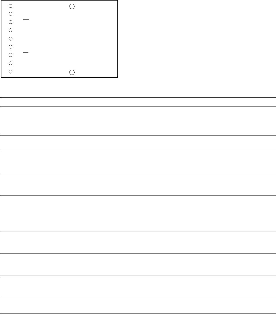
10
1 = V
EER
2 = RD
3 = RD
4 = SD
5 = V
CCR
6 = V
CCT
7 = TD
8 = TD
9 = V
EET
N/C
N/C
N/C = NO INTERNAL CONNECTION
(MOUNTING POSTS) - CONNECT
TO CHASSIS GROUND OR LEAVE
FLOATING, DO NOT CONNECT TO
SIGNAL GROUND.
TOP VIEW
Table 1. Pinout Table
Pin Symbol Functional Description
Mounting Studs The mounting studs are provided for transceiver mechanical attachment to the circuit boards, they are
embedded in the metalized plastic housing and are not connected to the transceiver internal circuit. They
should be soldered into plated-through holes on the printed circuit board and not connected to signal
ground.
1V
EER
Receiver Signal GroundDirectly connect this pin to receiver signal ground plane. Receiver V
EER
and trans-
mitter V
EET
can connect to a common circuit board ground plane.
2 RD+ Receiver Data Out
Terminate this high-speed, di erential, PECL output with standard PECL techniques at the follow-on
device input pin.
3 RD- Receiver Data Out Bar
Terminate this high-speed, di erential, PECL output with standard PECL techniques at the follow-on
device input pin.
4 SD Signal Detect
Normal input optical signal levels to the receiver result in a logic “1” output (V
OH
).Low input optical signal
levels to the receiver result in a fault condition indication shown by a logic “0” output (V
OL
).If Signal Detect
output is not used, leave it open-circuited.This Signal Detect output can be used to drive a PECL input on
an upstream circuit, such as, Signal Detect input or Loss of Signal-bar.
5V
CCR
Receiver Power Supply
Provide +5 V dc via the recommended receiver V
CCR
power supply lter circuit.Locate the power supply
lter circuit as close as possible to the V
CCR
pin.
6V
CCT
Transmitter Power Supply
Provide +5 V dc via the recommended transmitter V
CCT
power supply lter circuit.Locate the power supply
lter circuit as close as possible to the V
CCT
pin.
7 TD- Transmitter Data In Bar
Terminate this high-speed, di erential, Transmitter Data input with standard PECL techniques at the
transmitter input pin.
8 TD+ Transmitter Data InTerminate this high-speed, di erential, Transmitter Data input with standard PECL
techniques at the transmitter input pin.
9V
EET
Transmitter Signal GroundDirectly connect this pin to the transmitter signal ground plane. Transmitter
V
EET
and receiver V
EER
can connect to a common circuit board ground plane.

