LTM8020
7
8020fd
OPERATION
The LTM8020 is a standalone nonisolated step-down
switching DC/DC power supply. It can deliver up to
200mA of DC output current with only bulk external input
and output capacitors. This module provides a precisely
regulated output voltage programmable via one external
resistor from 1.25VDC to 5VDC. The input voltage range
is 4V to 36V. Given that the LTM8020 is a step-down con-
verter, make sure that the input voltage is high enough to
support the desired output voltage and load current. See
Block Diagram.
The LTM8020 contains a current mode controller, power
switching element, power inductor, power Schottky diode
and a modest amount of input and output capacitance.
For some applications, as shown in Table 1, no output
capacitor is necessary.
With its high performance current mode controller and
internal feedback loop compensation, the LTM8020 module
has sufficient stability margin and good transient perfor-
mance under a wide range of operating conditions with a
wide range of output capacitors, even all ceramic ones (X5R
or X7R). Current mode control provides cycle-by-cycle fast
current limit, and automatic current limiting protects the
module in the event of a short circuit or overload fault.
The LTM8020 is built upon a variable frequency control-
ler. The on time, off time and switching frequency are
dependent upon the input voltage, output voltage and
load current.
The drive circuit for the internal power switching element
is powered through the BIAS pin. Power this pin with at
least 3V.
The LTM8020 is equipped with two operating modes,
dependant upon the load current. When the load current
is sufficiently high, the LTM8020 will switch continuously
(see Figure 1a). If the load is very light, or if the input
voltage is high relative to the output voltage, the part will
operate in Burst Mode
®
operation, alternating between its
micropower and switching states to keep the output in
regulation and hold the power dissipation to a minimum
(See Figure 1b).
If the SHDN pin is grounded, all internal circuits are turned
off and V
IN
current reduces to the device leakage current,
typically a few nanoamps.
Figure 1. Output Voltage and Internal Inductor Current
V
OUT
20mV/DIV
I
L
100mA/DIV
1ms/DIV
V
OUT
20mV/DIV
I
L
100mA/DIV
5μs/DIV
8020 F01b
NO LOAD
10mA LOAD
(1b) Burst Mode Operation
V
OUT
20mV/DIV
I
L
100mA/DIV
1μs/DIV
V
OUT
20mV/DIV
I
L
100mA/DIV
1μs/DIV
(1a) Continuous Operation
8020 F1a
200mA LOAD
150mA LOAD
LTM8020
8
8020fd
For most applications, the design process is straight
forward, summarized as follows:
1. Look at Table 1 and find the row that has the desired
input range and output voltage.
2. Apply the C
IN
, C
OUT
, R
ADJ
and BIAS connection indicated
on that row.
While these component combinations have been tested for
proper operation, it is incumbent upon the user to verify
proper operation over the intended system’s line, load and
environmental conditions.
If an output voltage other than those listed in Table 1 is
desired, use the equation R
ADJ
= 623.75/(V
OUT
– 1.25),
where R
ADJ
is in kΩ. As a starting point, use values for
C
IN
and C
OUT
that correspond to the input voltage and
output voltage that most closely matches the intended
application, and verify proper operation over the system’s
line, load and environmental conditions.
Capacitor Selection Considerations
The C
IN
and C
OUT
capacitor values in Table 1 are the
minimum recommended values for the associated oper-
ating conditions. Applying capacitor values below those
indicated in Table 1 is not recommended, and may result
in undesirable operation. An input system bulk capacitor
is assumed. Using larger values is generally acceptable,
and can yield improved dynamic response, if it is neces-
sary. Again, it is incumbent upon the user to verify proper
operation over the intended system’s line, load and envi-
ronmental conditions.
Ceramic capacitors are small, robust and have very low
ESR. However, not all ceramic capacitors are suitable.
X5R and X7R types are stable over temperature and ap-
plied voltage and give dependable service. Other types,
including Y5V and Z5U have very large temperature and
voltage coefficients of capacitance. In an application cir-
cuit they may have only a small fraction of their nominal
capacitance resulting in much higher output voltage ripple
than expected.
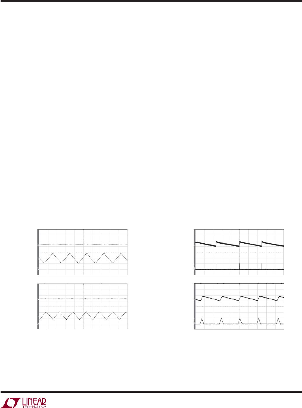
Ceramic capacitors are also piezoelectric. The LTM8020’s
switching frequency depends on the load current, and
at light loads it can excite a ceramic capacitor at audio
APPLICATIONS INFORMATION
frequencies, generating audible noise. Since the LTM8020
operates at a lower current limit during Burst Mode opera-
tion, the noise is typically very quiet to a casual ear.
If this audible noise is unacceptable, use a high performance
electrolytic capacitor at the output. The input capacitor can
be a parallel combination of a 2.2μF ceramic capacitor and
a low cost electrolytic capacitor.
A final precaution regarding ceramic capacitors concerns
the maximum input voltage rating of the LTM8020. A
ceramic input capacitor combined with trace or cable
inductance forms a high Q (under damped) tank circuit.
If the LTM8020 circuit is plugged into a live supply, the
input voltage can ring to twice its nominal value, possi-
bly exceeding the device’s rating. This situation is easily
avoided; see the Hot-Plugging Safely section.
Shorted Input Protection
Care needs to be taken in systems where the output will be
held high when the input to the LTM8020 is absent. This
may occur in battery charging applications or in battery
backup systems where a battery or some other supply
is diode ORed with the LTM8020’s output. If the V
IN
pin
is allowed to float and the SHDN pin is held high (either
by a logic signal or because it is tied to V
IN
), then the
LTM8020’s internal circuitry will pull its quiescent current
from its output. This is fine if your system can tolerate a
few milliamps in this state. If you ground the SHDN pin,
this quiescent current will drop to essentially zero. How-
ever, if the V
IN
pin is grounded while the output is held
high, then parasitic diodes inside the LTM8020 can pull
large currents from the output through the internal power
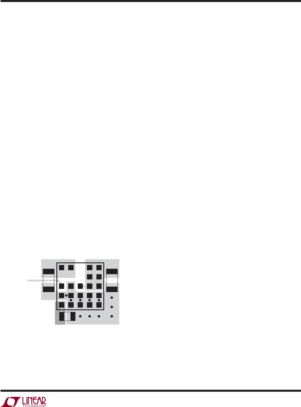
switch, possibly damaging the device. Figure 2 shows a
circuit that will run only when the input voltage is present
and that protects against a shorted or reversed input.
Figure 2. Diode D1 Prevents a Shorted Input from Discharging
a Backup Battery Tied to the Output, as Well as Protecting the
LTM8020 from a Reversed Input
V
IN
LTM8020
SHDN
V
IN
8020 F02
GND
D1
100k
1M
LTM8020
9
8020fd
APPLICATIONS INFORMATION
PCB Layout
Most of the headaches associated with PCB layout have
been alleviated or even eliminated by the high level of
integration of the LTM8020. The LTM8020 is never-the-
less a switching power supply, and care must be taken to
minimize EMI and ensure proper operation. Even with the
high level of integration, you may fail to achieve specified
operation with a haphazard or poor layout. See Figure 3
for a suggested layout.
Ensure that the grounding and heat sinking are acceptable.
A few rules to keep in mind are:
1. Place the C
IN
capacitor as close as possible to the V
IN
and GND connection of the LTM8020.
2. Place the C
OUT
capacitor as close as possible to the
V
OUT
and GND connection of the LTM8020.
3. Place the C
IN
and C
OUT
capacitors such that their
ground current flows directly adjacent or underneath
the LTM8020.
4. Connect all of the GND connections to as large a copper
pour or plane area as possible on the top layer. Avoid
breaking the ground connection between the external
components and the LTM8020.
5. The copper pours also serve as the heat sink for the
LTM8020. Place several vias in the GND plane to act as
heat pipes to other layers of the printed circuit board.
Positive-to-Negative Voltage Regulation
The LTM8020 can generate a negative output by tying the
V
OUT
pads to system ground and connecting GND as shown
in the Typical Applications section. In this configuration,
SHDN must be level shifted or referenced to GND, and the
available output current may be reduced.
Hot-Plugging Safely
The small size, robustness and low impedance of ceramic
capacitors make them an attractive option for the input
bypass capacitor of LTM8020. However, these capacitors
can cause problems if the LTM8020 is plugged into a live
supply (see Linear Technology Application Note 88 for
a complete discussion). The low loss ceramic capacitor
combined with stray inductance in series with the power
source forms an under damped tank circuit, and the volt-
age at the V
IN
pin of the LTM8020 can ring to twice the
nominal input voltage, possibly exceeding the LTM8020’s
rating and damaging the part. If the input supply is poorly
controlled or the user will be plugging the LTM8020 into
an energized supply, the input network should be designed
to prevent this overshoot. Figure 4 shows the waveforms
that result when an LTM8020 circuit is connected to a 24V
supply through six feet of 24-gauge twisted pair. The first
plot is the response with a 2.2μF ceramic capacitor at the
input. The input voltage rings as high as 35V and the input
current peaks at 20A. One method of damping the tank
circuit is to add another capacitor with a series resistor to
the circuit. In Figure 4b an aluminum electrolytic capacitor
has been added. This capacitors high equivalent series
resistance damps the circuit and eliminates the voltage
overshoot. The extra capacitor improves low frequency
ripple filtering and can slightly improve the efficiency of the
circuit, though it is likely to be the largest component in the
circuit. An alternative solution is shown in Figure 4c. A 1Ω
resistor is added in series with the input to eliminate the
voltage overshoot (it also reduces the peak input current).
A 0.1μF capacitor improves high frequency filtering. This
solution is smaller and less expensive than the electrolytic
capacitor. For high input voltages its impact on efficiency
is minor, reducing efficiency less than one-half percent for
a 5V output at full load operating from 24V.
Figure 3. Layout Showing Suggested External
Components, GND Plane and Thermal Vias
GND
VIAs TO GND PLANE
V
OUT
ADJ
COPPER
BIAS
SHDN
V
IN
C
OUT
R
ADJ
C
IN
8020 F03

LTM8020IV#PBF

Mfr. #:
Manufacturer:
Analog Devices / Linear Technology
Description:
Switching Voltage Regulators 36V, 200mA Step-down Module Regulator
Lifecycle:
New from this manufacturer.
Delivery:
DHL FedEx Ups TNT EMS
Payment:
T/T Paypal Visa MoneyGram Western Union

Products related to this Datasheet