Data Sheet: JN5139-xxx-Myy
IEEE802.15.4/ZigBee Module Family
JN-DS-JN5139-xxx-Myy 1v6 © NXP Laboratories UK 2010
Overview Overview
Features: Module
The JN5139-xxx-Myy family is a range of surface mount modules that enable users to
implement systems using IEEE802.15.4, 6LoWPAN, JenNet or ZigBee with minimum
time to market and at the lowest cost. They remove the need for expensive and
lengthy development of custom RF board designs and test suites. The modules use
Jennic’s JN5139 wireless microcontroller to provide a comprehensive solution with
high radio performance and all RF components included. All that is required to
develop and manufacture wireless control or sensing products is to connect a power
supply and peripherals such as switches, actuators and sensors, considerably
simplifying product development.
2.4GHz IEEE802.15.4 & ZigBee
compatible
2.7-3.6V operation
Sleep current (with active sleep
timer) 2.6µA
JN5139-xxx-M00/01/03
up to 1km range (ext antenna)
M00: on board antenna
M01: SMA connector
M03: uFl connector
Three basic hardware module variants are available: JN5139-xxx-M00 with an
integrated antenna, JN5139-xxx-M01/M03 with an antenna connector and JN5139-
xxx-M02/M04 with a power amplifier and LNA for extended range. Variants are
available either with a ZigBee network stack (JN5139-Z01-Myy) or supporting the
other stacks (JN5139-001-Myy).
o Receiver sensitivity –96dBm
o TX power +2.5dBm
o TX current 37mA
o RX current 37mA
o 18x30mm
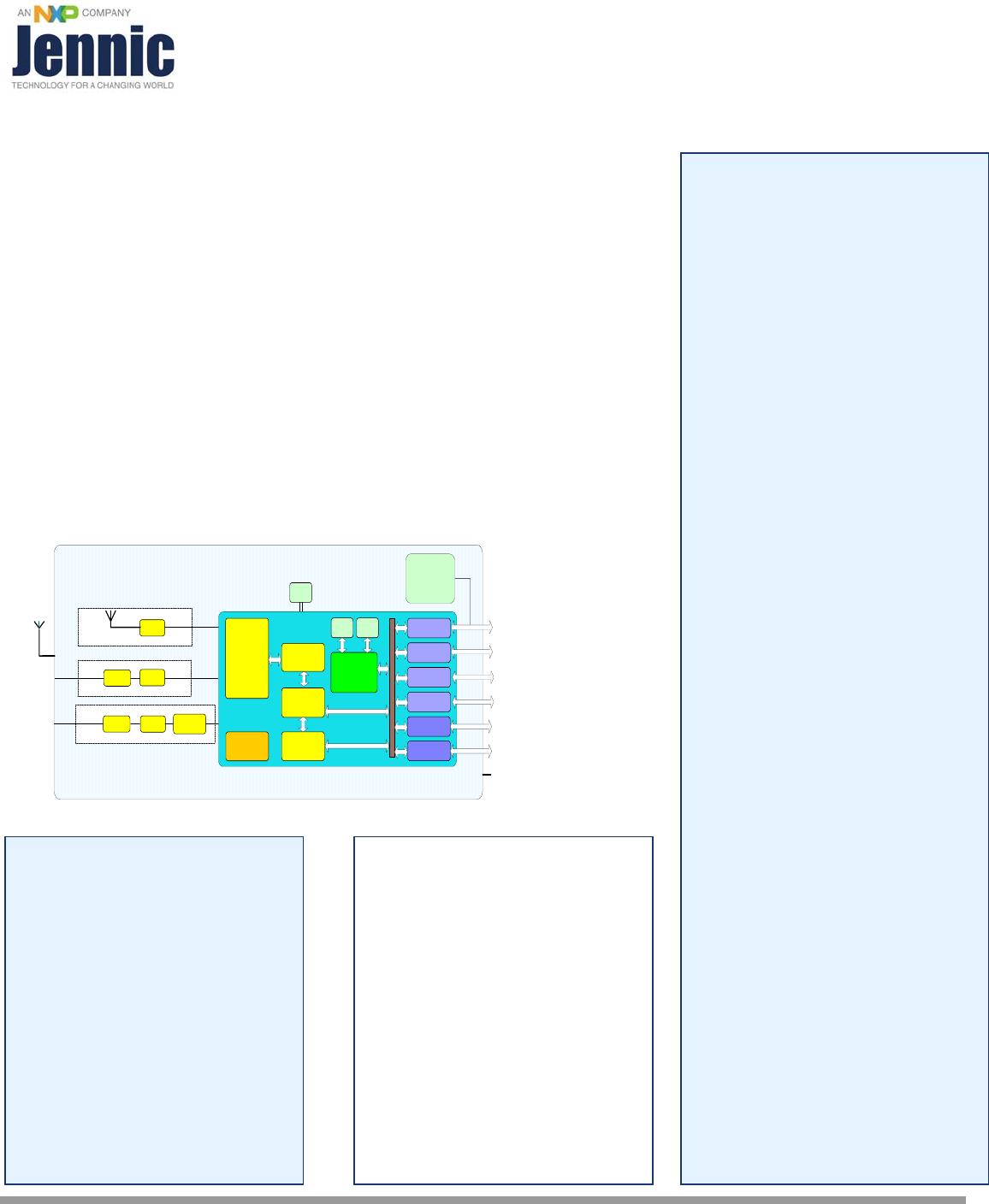
Module Block Diagram Module Block Diagram
JN5139-xxx-M02/04
up to 4km range
M02: SMA connector
M04: uFl connector
Ti mer s
UARTs
12-bit ADC,
comparators
11-bi t DACs,
temp sensor
2-wire serial
SPI
RAM
96kB
128-bit AES
Enc ry pt i on
Accel erator
2. 4GHz
Radio
ROM
192kB
RISC CPU
Power
Management
XTAL
O- QP SK
Mod e m
IEEE802. 15.4
MAC
Accel erator
128kB Serial
Flash Memory
JN5139 chip
Power
Bal un
Connector
Bal un
Ceramic Antenna
Bal unConnector PA / LNA
Ext e rn al
An te n n a
M00 Option
M01/03 Option
M02/04 Option
o Receiver sensitivity -100dBm
o 19dBm TX power
o TX current 125mA
o RX current 45mA
o 18x41mm
Features: Microcontroller
16MHz 32-bit RISC CPU
96kB RAM, 192kB ROM
4-input 12-bit ADC, 2 11-bit
DACs, 2 comparators,
temperature sensor
2 Application timer/counters,
3 system timers
2 UARTs (one for in-system
debug)
SPI port with 5 selects
2-wire serial interface
21 GPIO
Evaluation kits available with full,
unlimited, Software Development
Kit
Temperature range
-20°C to +70°C
Lead-free and RoHS compliant
Benefits Applications
Microminiature module solutions
Robust and secure low power
wireless applications
Ready to use in products
Wireless sensor networks,
particularly IEEE802.15.4 /
ZigBee systems
Minimises product development
time
No RF test required for systems
Home and commercial building
automation
Compliant with FCC part 15
rules, IC Canada RSS 210e,
ETSI ETS 300-328 and Japan
ARIB STD-T66
Home networks
Toys and gaming peripherals
Production volumes supplied
pre-programmed with
application software
Industrial systems
Telemetry and utilities
(e.g. AMR)
Contents
1. Introduction 3
3 1.1. Variants
3 1.2. Regulatory Approvals
2. Specifications 4
3. Product Development 5
3.1. JN5139 Single Chip Wireless Microcontroller 5
4. Pin Configurations 6
7 4.1. Pin Assignment
4.2. Pin Descriptions 8
4.2.1 Power Supplies 8
8 4.2.2 SPI Memory Connections
5. Electrical Characteristics 9
9 5.1. Maximum Ratings
9 5.2. Reflow Profile
5.3. Operating Conditions 10
Appendix A Additional Information 11
11 A.1 Outline Drawing
16 A.2 Module PCB Footprint
17 A.3 Ordering Information
18 A.4 Tape and Reel Information:
18 A.4.1 Tape Orientation and dimensions
A.4.2 Cover tape details 18
A.4.3 Leader and Trailer 19
19 A.4.4 Reel Dimensions:
20 A.5 Related Documents
20 A.6 Federal Communication Commission Interference Statement
A.6.1 Antennas approved by FCC for use with JN5139 modules 21
22 A.6.2 High Power Module usage limitation
A.6.3 FCC End Product Labelling 22
23 A.7 European R & TTE Directive 1999/5/EC Statement
24 A.8 Industry Canada Statement
24 A.8.1 Industry Canada End Product Labelling
24 A.9 RoHS Compliance
A.10 Status Information 25
25 A.11 Disclaimers
26 A.12 Version Control
ii JN-DS-JN5139-xxx-Myy 1v6 © NXP Laboratories UK 2010
1. Introduction
The JN5139-xxx-Myy module family provides designers with a ready made component which allows IEEE802.15.4 [1]
wireless applications, using Jennic’s JenNet networking protocol or ZigBee, to be quickly and easily included in
product designs. The modules integrate all of the RF components required, removing the need to perform expensive
RF design and test. Products can be designed by simply connecting sensors and switches to the module IO pins.
The modules use Jennic’s single chip IEEE802.15.4 Wireless Microcontroller, allowing designers to make use of the
extensive chip development support material. Hence, this range of modules allows designers to bring wireless
applications to market in the minimum time with significantly reduced development effort and cost.
Three module hardware variants are available: JN5139-xxx-M00 (standard module with on board ceramic antenna),
JN5139-xxx-M01 (standard module with SMA connector for use with external antennae – recommended for
evaluation use) and JN5139-xxx-M02 (high RF power, improved sensitivity module for evaluation of extended range
applications). For volume production applications, uFL connector variants are provided (-M03 standard power and –
M04 high power). These devices, together with the –M00 variants have FCC modular approvals. Each of these
modules can be supplied with a range of protocol stacks, including JenNet for most tree and linear networks,
IEEE802.15.4 protocol for point-to-point and star applications and a ZigBee mesh networking stack. The variants
available are described below.
1.1. Variants
1.2. Regulatory Approvals
All module types have been tested against the requirements of European standard ETS 300 328 v1.7.1 and a
Notified Body statement of opinion for this standard is available on request. The High Power modules with M02 or
M04 suffix are approved for use in Europe with reduced output power: +10dBm EIRP is the maximum permitted in
Europe. They must not be used with PHY_PIB_ATTR_TX_POWER set above 50 See
[3] JN-RM-2002 802.15.4
Stack API
.
Additionally, modules with M00, M03 and M04 suffixes have received FCC “Modular Approvals”, in compliance with
CFR 47 FCC part 15 regulations and in accordance to FCC Public notice DA00-1407. The modules are approved for
use with a number of antennas, refer to section A.6.1 for details. See Appendix A.6 for details on the conditions
applying to this modular approval. The modular approvals notice and test reports are available on request.
The high power module variant is classified as ‘mobile’ device pursuant with FCC § 2.1091 and must not be used at a
distance of less than 20 cm (8”) from any person.
In addition, all modules have Industry Canada RSS 210e Issue 7 (June 2007) certification.
Variant Description FCCID Industry Canada ID
IC: 7438A-CYO5139M0
JN5139-001-M00 IEEE802.15.4 stack, ceramic antenna TYOJN5139M0
IC: 7438A-CYO5139M0
JN5139-Z01-M00 ZigBee stack, ceramic antenna TYOJN5139M0
IEEE802.15.4 stack, SMA connector - for
evaluation
IC: 7438A-CYO5139M6
JN5139-001-M01
N/A
ZigBee stack, SMA connector – for
evaluation
IC: 7438A-CYO5139M6
JN5139-Z01-M01 N/A
High Power, IEEE802.15.4 stack, SMA
connector – for evaluation
IC: 7438A-CYO5139M4
JN5139-001-M02 N/A
High Power, ZigBee stack, SMA connector
– for evaluation
IC: 7438A-CYO5139M4
JN5139-Z01-M02
N/A
IC: 7438A-CYO5139M6
JN5139-001-M03 IEEE802.15.4 stack, uFl connector TYOJN5139M3
IC: 7438A-CYO5139M6
JN5139-Z01-M03 ZigBee stack, uFl connector TYOJN5139M3
High Power, IEEE802.15.4 stack, uFl
connector
IC: 7438A-CYO5139M4
JN5139-001-M04 TYOJN5139M4
IC: 7438A-CYO5139M4
JN5139-Z01-M04 High Power, ZigBee stack, uFl connector TYOJN5139M4
© NXP Laboratories UK 2010 JN-DS-JN5139-xxx-Myy 1v6 3

JN5139-001-M/01R1V

Mfr. #:
Manufacturer:
NXP Semiconductors
Description:
Zigbee Modules (802.15.4) WIRELESS MCU IEEE802.15.4 TRNSCVR
Lifecycle:
New from this manufacturer.
Delivery:
DHL FedEx Ups TNT EMS
Payment:
T/T Paypal Visa MoneyGram Western Union