Micrel, Inc. MIC2940A/2941A
July 2007
7
M9999-071307
Application Information
External Capacitors
A 10µF (or greater) capacitor is required between the
MIC2940A output and ground to prevent oscillations due
to instability. Most types of tantalum or aluminum
electrolytics will be adequate; film types will work, but
are costly and therefore not recommended. Many
aluminum electrolytics have electrolytes that freeze at
about –30°C, so solid tantalums are recommended for
operation below –25°C. The important parameters of the
capacitor are an effective series resistance of about 5Ω
or less and a resonant frequency above 500kHz. The
value of this capacitor may be increased without limit.
At lower values of output current, less output
capacitance is required for output stability. The capacitor
can be reduced to 3.3µF for current below 100mA or
2.2µF for currents below 10mA. Adjusting the MIC2941A
to voltages below 5V runs the error amplifier at lower
gains so that more output capacitance is needed. For
the worst-case situation of a 1.25A load at 1.23V output
(Output shorted to Adjust) a 22µF (or greater) capacitor
should be used.
The MIC2940A will remain stable and in regulation with
load currents ranging from 5mA on up to the full 1.25A
rating. The external resistors of the MIC2941A version
may be scaled to draw this minimum load current.
A 0.22µF capacitor should be placed from the
MIC2940A input to ground if there is more than 10
inches of wire between the input and the AC filter
capacitor or if a battery is used as the input.
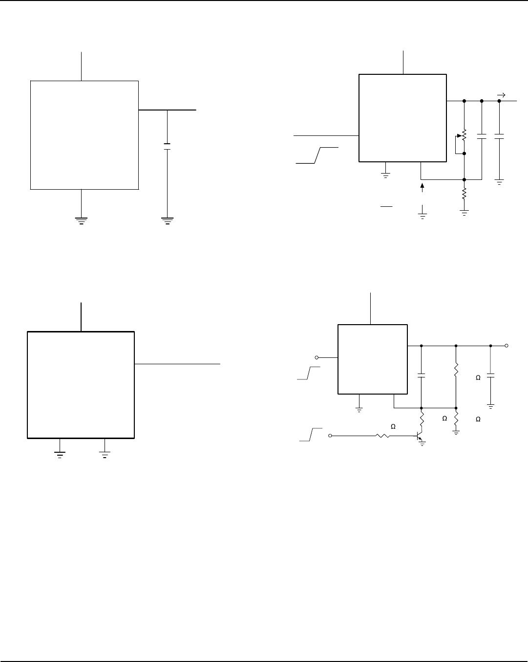
Programming the Output Voltage (MIC2941A)
The MIC2941A may be programmed for any output
voltage between its 1.235V reference and its 26V
maximum rating. An external pair of resistors is required,
as shown in Figure 3.
V
OUT
= V
REF
x { 1 + R
1
/R
2
} – |I
FB
| R
1
where V
REF
is the nominal 1.235 reference voltage and
I
FB
is the Adjust pin bias current, nominally 20nA. The
minimum recommended load current of 1µA forces an
upper limit of 1.2MΩ on the value of R
2
, if the regulator
must work with no load (a condition often found in
CMOS in standby), I
FB
will produce a –2% typical error in
V
OUT
which may be eliminated at room temperature by
trimming R
1
. For better accuracy, choosing R
2
= 100kΩ
reduces this error to 0.17% while increasing the resistor
program current to 12µA. Since the MIC2941A typically
draws 100µA at no load with SHUTDOWN open-
circuited, this is a negligible addition.
Reducing Output Noise
In reference applications it may be advantageous to
reduce the AC noise present at the output. One method
is to reduce the regulator bandwidth by increasing the
size of the output capacitor. This is relatively inefficient,
as increasing the capacitor from 1µF to 220µF only
decreases the noise from 430µV to 160µV
RMS
for a
100kHz bandwidth at 5V output. Noise can be reduced
by a factor of four with the MIC2941A by adding a
bypass capacitor across R
1
. Pick
200HzR2
1
C
1
BYPASS
π
≅
or about 0.01µF. When doing this, the output capacitor
must be increased to 22µF to maintain stability. These
changes reduce the output noise from 430µV to
100µV
RMS
for a 100kHz bandwidth at 5V output. With the
bypass capacitor added, noise no longer scales with
output voltage so that improvements are more dramatic
at higher output voltages.
Automotive Applications
The MIC2940A is ideally suited for automotive
applications for a variety of reasons. It will operate over
a wide range of input voltages with very low dropout
voltages (40mV at light loads), and very low quiescent
currents (240µA typical). These features are necessary
for use in battery powered systems, such as
automobiles. It is a “bulletproof” device with the ability to
survive both reverse battery (negative transients up to
20V below ground), and load dump (positive transients
up to 60V) conditions. A wide operating temperature
range with low temperature coefficients is yet another
reason to use these versatile regulators in automotive
designs.
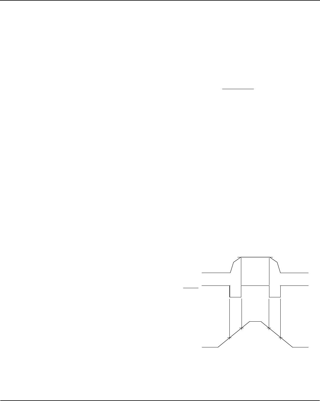
NOT *
VALID
NOT *
VALID
OUTPUT
VOLTAGE
4.75V
ERROR
INPUT
VOLTAGE
5V
1.3V
Figure 1. ERROR Output Timing