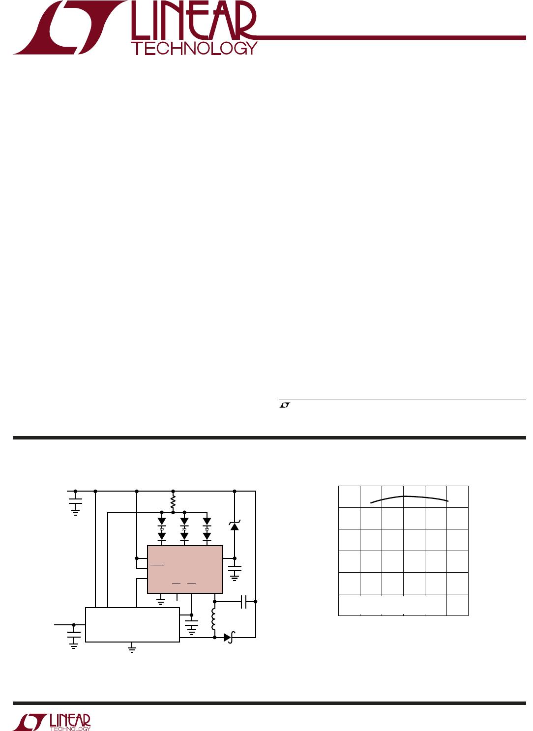
LT3003
2
3003fa
ELECTRICAL CHARACTERISTICS
PACKAGE/ORDER INFORMATIONABSOLUTE MAXIMUM RATINGS
V
IN
............................................................................40V
LED1, LED2, LED3 ....................................................48V
V
MAX
, SHDN ..............................................................48V
V
IN
– V
EE
...................................................................36V
V
EE
............................................................................36V
PWM .........................................................................15V
OT1, OT2 .....................................................................6V
Operating Junction Temperature Range
(Notes 2, 3, 4) ........................................ –40°C to 125°C
Storage Temperature Range ................... –65°C to 150°C
Lead Temperature (Soldering, 10 sec) .................. 300°C
(Note 1)
The
● denotes the specifi cations which apply over the full operating
temperature range, otherwise specifi cations are at T
A
= 25°C. PWM = 1V, V
MAX
= 4V, V
IN
= 3V, V
EE
= 0V, I
LED2
= 100mA,
OT1 = OT2 = Open, SHDN = V
IN
.
PARAMETER CONDITIONS MIN TYP MAX UNITS
V
IN
Operational Input Voltage V
EE
= 0V, I
LED1,2,3
= 100mA
V
EE
= 4V, I
LED1,2,3
= 100mA
●
336
40
V
V
Minimum (V
IN
– V
EE
)V
EE
= 0V to 36V 2.7 3 V
V
IN
Quiescent Current PWM = 1V, I
LED1,2,3
= 100mA
PWM = 0V, V
LED1
= V
LED2
= V
LED3
10.5
470 600
mA
µA
V
IN
Shutdown Current SHDN = 0V, I
LED1,2,3
= 0mA 2 4 10 µA
V
MAX
Quiescent Current PWM = 1V, I
LED2
= 100mA
PWM = 0V, V
LED1
= V
LED2
= V
LED3
55
20
90
300
µA
nA
SHDN Pin Threshold I
LED2
= 100mA, V
LED1
= V
LED2
= V
LED3
●
0.25 0.7 1 V
LED Current Matching I
LED2
= 350mA, V
LED1
= V
LED2
= V
LED3
–3 0 +3 %
|LED2 – LED1|, |LED2 – LED3| LED Current
Matching with LED Pin Voltage Mismatch
I
LED2
= 350mA,
(|V
LED2
– V
LED1
| + |V
LED2
– V
LED3
|) = 700mV
–3.5 0.5 +3.5 %
LED Pin Voltage I
LED2
= 100mA 0.7 0.8 0.9 V
LED1, LED2, LED3 Maximum Current V
LED1,2,3
< 1.5V 375 500 550 mA
LED1, LED2, LED3 Maximum Leakage Current PWM = 0V, V
LED1,2,3
= 48V 0.1 1 µA
PWM Switching Threshold I
LED1,2,3
= 100mA
●
0.3 0.5 0.7 V
Turn-On Delay (PWM On to I
LED
On) PWM = 0V to 1V, I
LED
> 50mA 2 µs
V
EE
Pin Current in Buck Mode PWM = 0V, V
MAX
= 40V, V
IN
= 39V, V
EE
= 36V 0.1 1 µA
Overtemperature Sense Point (OT1, OT2) (Note 4) 125 °C
Overtemperature Hysteresis Point (Note 5) –6° from Overtemp
Sense Point
°C
OT1 Pull-Down Current OT1 = 0.3V (Note 4) 100 µA
1
2
3
4
5
LED1
LED2
LED3
V
MAX
V
IN
10
9
8
7
6
V
EE
SHDN
OT2
OT1
PWM
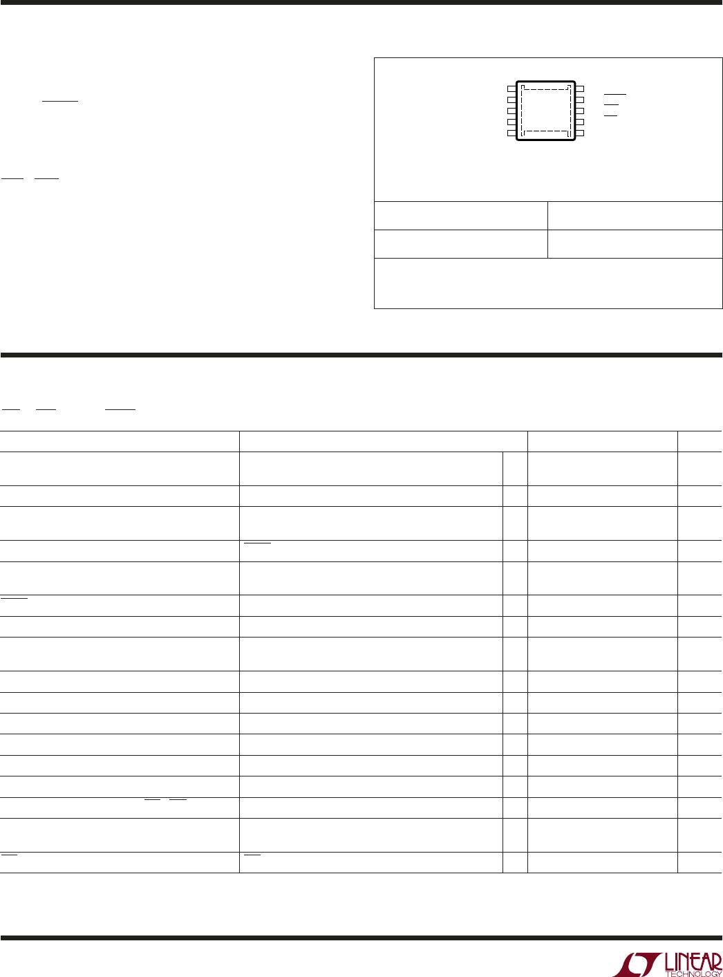
TOP VIEW
11
MSE PACKAGE
10-LEAD PLASTIC MSOP
T
JMAX
= 125°C, θ
JA
= 35°C/W
EXPOSED PAD (PIN 11) IS GND, MUST BE SOLDERED TO PCB
ORDER PART NUMBER MSE PART MARKING
LT3003EMSE LTCFF
Order Options Tape and Reel: Add #TR
Lead Free: Add #PBF Lead Free Tape and Reel: Add #TRPBF
Lead Free Part Marking: http://www.linear.com/leadfree/
Consult LTC Marketing for parts specifi ed with wider operating temperature ranges.