LM158, LM158A, LM258, LM258A
LM358, LM358A, LM2904, LM2904Q
DUAL OPERATIONAL AMPLIFIERS
SLOS068E JUNE 1976 REVISED SEPTEMBER 2002
4
POST OFFICE BOX 655303 DALLAS, TEXAS 75265
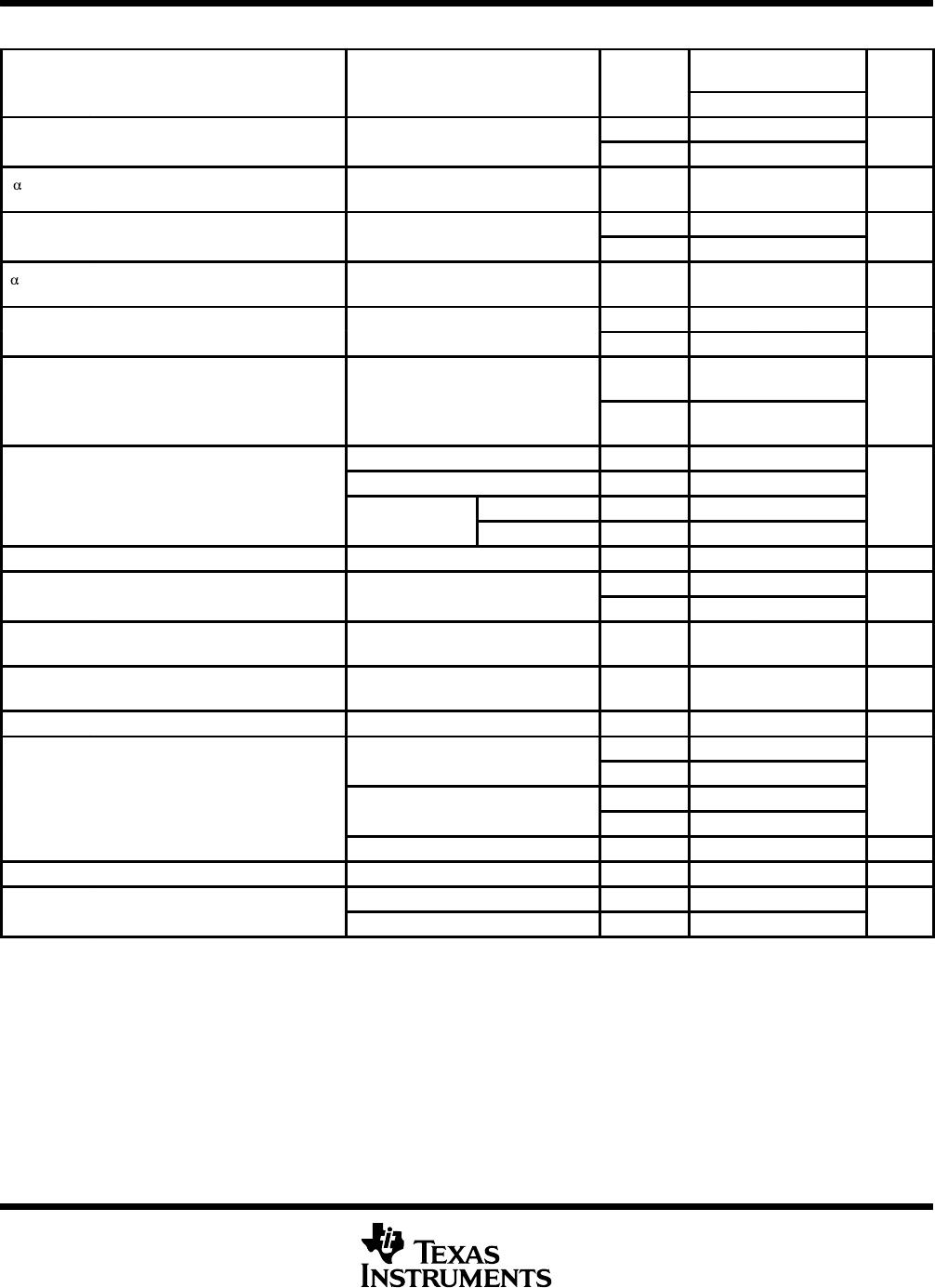
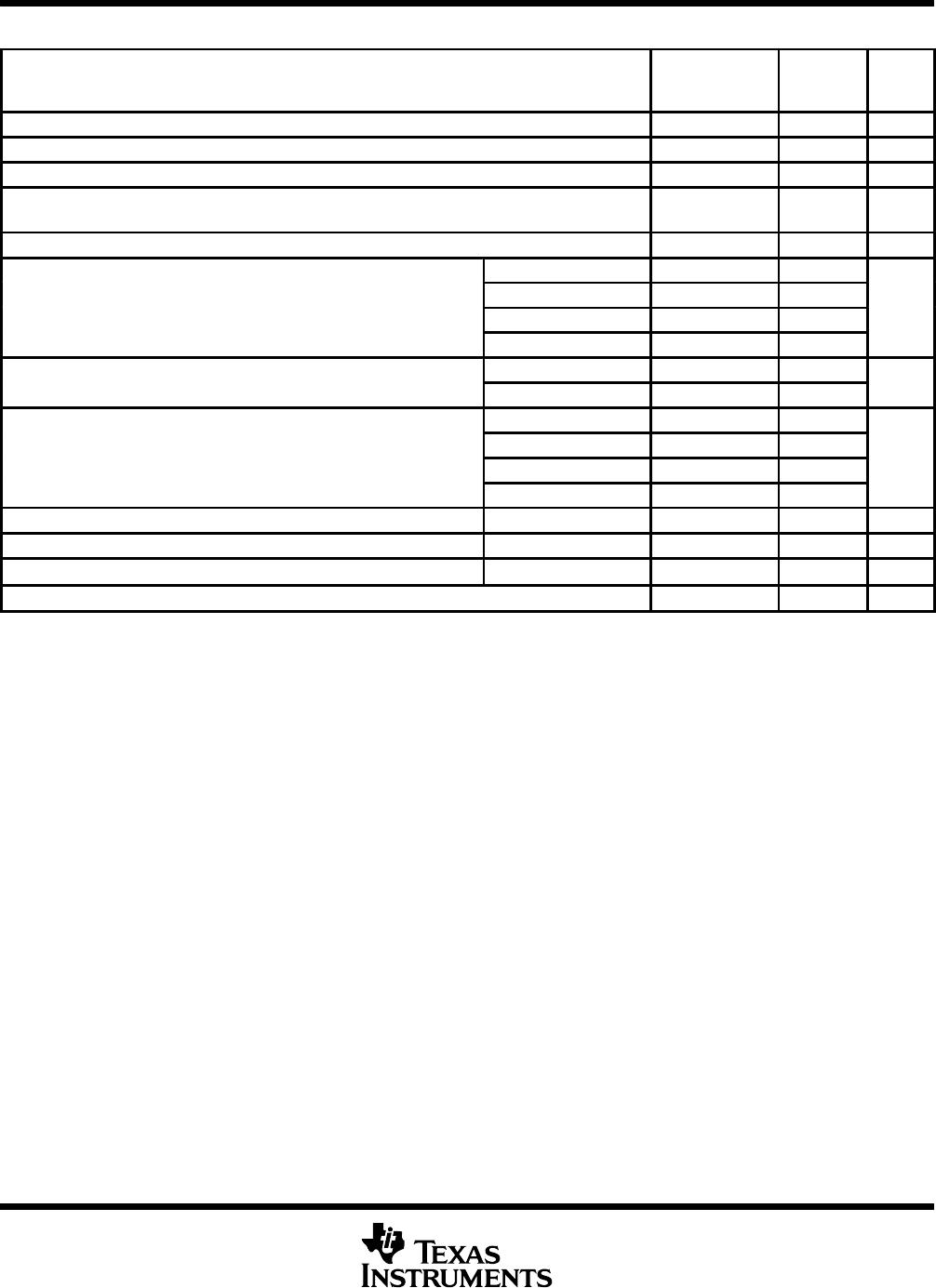
absolute maximum ratings over operating free-air temperature range (unless otherwise noted)
LM158, LM158A
LM258, LM258A
LM358, LM358A
LM2904
LM2904Q
UNIT
Supply voltage, V
CC
(see Note 1) 32 26 V
Differential input voltage, V
ID
(see Note 2) ±32 ±26 V
Input voltage, V
I
(either input) 0.3 to 32 0.3 to 26 V
Duration of output short circuit (one amplifier) to ground
at (or below) 25°C free-air temperature (V
CC
15 V) (see Note 3)
Unlimited Unlimited
Operating virtual junction temperature, T
J
150 150 °C
θ
D package 97 97
Package thermal im
p
edance θ
JA
(see Notes 4 and 5)
P package 85 85
°
C/W
Package
thermal
impedance
,
θ
JA
(see
Notes
4
and
5)
PS package 95 95
°C/W
PW package 149 149
Package thermal im
p
edance θ
JC
(see Notes 6 and 7)
FK package 5.61
°C/W
Package
thermal
impedance
,
θ
JC
(see
Notes
6
and
7)
JG package 14.5
°C/W
LM158, LM158A 55 to 125
O
p
erating free air tem
p
erature range T
A
LM258, LM258A 25 to 85
°C
Operating
free
-
air
temperature
range
,
T
A
LM358, LM358A 0 to 70
°C
LM2904, LM2904Q 40 to 125
Case temperature for 60 seconds FK package 260 °C
Lead temperature 1,6 mm (1/16 inch) from case for 60 seconds JG package 300 300 °C
Lead temperature 1,6 mm (1/16 inch) from case for 10 seconds P package 260 260 °C
Storage temperature range, T
stg
65 to 150 65 to 150 °C
Stresses beyond those listed under absolute maximum ratings may cause permanent damage to the device. These are stress ratings only, and
functional operation of the device at these or any other conditions beyond those indicated under recommended operating conditions is not
implied. Exposure to absolute-maximum-rated conditions for extended periods may affect device reliability.
NOTES: 1. All voltage values, except differential voltages and V
CC
specified for measurement of I
OS
, are with respect to the network ground
terminal.
2. Differential voltages are at IN+ with respect to IN.
3. Short circuits from outputs to V
CC
can cause excessive heating and eventual destruction.
4. Maximum power dissipation is a function of T
J
(max), θ
JA
, and T
A
. The maximum allowable power dissipation at any allowable
ambient temperature is P
D
= (T
J
(max) T
A
)/θ
JA
. Operating at the absolute maximum T
J
of 150°C can affect reliability.
5. The package thermal impedance is calculated in accordance with JESD 51-7.
6. Maximum power dissipation is a function of T
J
(max), θ
JC
, and T
C
. The maximum allowable power dissipation at any allowable case
temperature is P
D
= (T
J
(max) T
C
)/θ
JC
. Operating at the absolute maximum T
J
of 150°C can affect reliability.
7. The package thermal impedance is calculated in accordance with MIL-STD-883.
LM158, LM158A, LM258, LM258A
LM358, LM358A, LM2904, LM2904Q
DUAL OPERATIONAL AMPLIFIERS
SLOS068E JUNE 1976 REVISED SEPTEMBER 2002
5
POST OFFICE BOX 655303 DALLAS, TEXAS 75265
electrical characteristics at specified free-air temperature, V
CC
= 5 V (unless otherwise noted)
PARAMETER
TEST CONDITIONS
T
LM158
LM258
LM358
UNIT
MIN TYP
§
MAX MIN TYP
§
MAX
V
IO
In
p
ut offset voltage
V
CC
= 5 V to MAX,
V
IC
V
ICR( i )
25°C 3 5 3 7
mV
V
IO
Input
offset
voltage
V
IC
=
V
ICR(min)
,
V
O
= 1.4 V
Full range 7 9
mV
V
IO
Average temperature
coefficient of
input offset voltage
Full range 7 7 µV/°C
I
IO
In
p
ut offset current
V
O
=14V
25°C 2 30 2 50
nA
I
IO
Input
offset
current
V
O
=
1
.
4
V
Full range 100 150
nA
I
IO
Average temperature
coefficient of
input offset current
Full range 10 10 pA/°C
I
IB
In
p
ut bias current
V
O
=14V
25°C 20 150 20 250
nA
I
IB
Input
bias
current
V
O
=
1
.
4
V
Full range 300 500
nA
V
ICR
Common-mode
V
CC
=5VtoMAX
25°C
0 to
V
CC
1.5
0 to
V
CC
1.5
V
V
ICR
input voltage range
V
CC
=
5
V
to
MAX
Full range
0 to
V
CC
2
0 to
V
CC
2
V
R
L
2 k 25°C V
CC
1.5 V
CC
1.5
V
OH
Hi
g
h-level
R
L
10 k
25°C
V
V
OH
g
output voltage
V
CC
= MAX
R
L
= 2 k Full range 26 26
V
V
CC
=
MAX
R
L
10 k Full range 27 28 27 28
V
OL
Low-level
output voltage
R
L
10 k Full range 5 20 5 20 mV
A
VD
Large-signal
differential
V
CC
= 15 V,
V
O
1Vto11V
25°C 50 100 25 100
V/mV
A
VD
diff
eren
ti
a
l
voltage amplification
V
O
=
1
V
t
o
11
V
,
R
L
= 2 k
Full range 25 15
V/mV
CMRR
Common-mode
rejection ratio
V
CC
= 5 V to MAX,
V
IC
= V
ICR(min)
25°C 70 80 65 80 dB
k
SVR
Supply-voltage
rejection ratio
(V
DD
/V
IO
)
V
CC
= 5 V to MAX 25°C 65 100 65 100 dB
V
O1
/V
O2
Crosstalk attenuation f = 1 kHz to 20 kHz 25°C 120 120 dB
V
CC
= 15 V, V
ID
= 1 V,
25°C 20 30 20 30
CC
,
ID
,
V
O
= 0
Full range 10 10
mA
I
O
Output current
V
CC
= 15 V, V
ID
= 1 V,
25°C 10 20 10 20
mA
CC
,
ID
,
V
O
= 15 V
Full range 5 5
V
ID
= 1 V, V
O
= 200 mV 25°C 12 30 12 30 µA
I
OS
Short-circuit
output current
V
CC
at 5 V, GND at 5 V,
V
O
= 0
25°C ±40 ±60 ±40 ±60 mA
Su
pp
ly current
V
O
= 2.5 V, No load Full range 0.7 1.2 0.7 1.2
I
CC
Supply
current
(two amplifiers)
V
CC
= MAX, V
O
= 0.5 V,
No load
Full range 1 2 1 2
mA
All characteristics are measured under open-loop conditions with zero common-mode input voltage, unless otherwise specified. MAX V
CC
for
testing purposes is 26 V for the LM2904 and 30 V for others.
Full range is 55°C to 125°C for LM158, 25°C to 85°C for LM258, 0°C to 70°C for LM358, and 40°C to 125°C for LM2904 and LM2904Q.
§
All typical values are at T
A
= 25°C.
LM158, LM158A, LM258, LM258A
LM358, LM358A, LM2904, LM2904Q
DUAL OPERATIONAL AMPLIFIERS
SLOS068E JUNE 1976 REVISED SEPTEMBER 2002
6
POST OFFICE BOX 655303 DALLAS, TEXAS 75265
electrical characteristics at specified free-air temperature, V
CC
= 5 V (unless otherwise noted)
PARAMETER
TEST CONDITIONS
T
A
LM2904
LM2904Q
UNIT
A
MIN TYP
§
MAX
V
IO
In
p
ut offset voltage
V
CC
= 5 V to MAX,
25°C 3 7
mV
V
IO
Input
offset
voltage
CC
,
V
IC
= V
ICR(min)
, V
O
= 1.4 V
Full range 10
mV
V
IO
Average temperature coefficient of
input offset voltage
Full range 7 µV/°C
I
IO
In
p
ut offset current
V
O
=14V
25°C 2 50
nA
I
IO
Input
offset
current
V
O
=
1
.
4
V
Full range 300
nA
I
IO
Average temperature coefficient of
input offset current
Full range 10 pA/°C
I
IB
In
p
ut bias current
V
O
=14V
25°C 20 250
nA
I
IB
Input
bias
current
V
O
=
1
.
4
V
Full range 500
nA
V
ICR
Common mode in
p
ut voltage range
V
CC
=5VtoMAX
25°C
0 to
V
CC
1.5
V
V
ICR
Common
-
mode
input
voltage
range
V
CC
=
5
V
to
MAX
Full range
0 to
V
CC
2
V
R
L
2 k 25°C
V
OH
High level out
p
ut voltage
R
L
10 k 25°C V
CC
1.5
V
V
OH
High
-
level
output
voltage
V
CC
= MAX
R
L
= 2 k Full range 26
V
V
CC
=
MAX
R
L
10 k Full range 23 24
V
OL
Low-level output voltage R
L
10 k Full range 5 20 mV
A
VD
Lar
g
e-si
g
nal differential V
CC
= 15 V, V
O
= 1 V to 11 V,
25°C 25 100
V/mV
A
VD
gg
voltage amplification
CC
,
O
,
R
L
= 2 k
Full range 15
V/mV
CMRR Common-mode rejection ratio
V
CC
= 5 V to MAX,
V
IC
= V
ICR(min)
25°C 50 80 dB
k
SVR
Supply-voltage rejection ratio
(V
DD
/V
IO
)
V
CC
= 5 V to MAX 25°C 65 100 dB
V
O1
/V
O2
Crosstalk attenuation f = 1 kHz to 20 kHz 25°C 120 dB
V
CC
=15V V
ID
=1V V
O
=0
25°C 20 30
V
CC
=
15
V
,
V
ID
=
1
V
,
V
O
=
0
Full range 10
mA
I
O
Output current
V
CC
=15V V
ID
= 1V V
O
=15V
25°C 10 20
mA
V
CC
=
15
V
,
V
ID
=
1
V
,
V
O
=
15
V
Full range 5
V
ID
= 1 V, V
O
= 200 mV 25°C 30 µA
I
OS
Short-circuit output current V
CC
at 5 V, GND at 5 V, V
O
= 0 25°C ±40 ±60 mA
I
CC
Su
pp
ly current (two am
p
lifiers)
V
O
= 2.5 V, No load Full range 0.7 1.2
mA
I
CC
Supply
current
(two
amplifiers)
V
CC
= MAX, V
O
= 0.5 V, No load Full range 1 2
mA
All characteristics are measured under open-loop conditions with zero common-mode input voltage, unless otherwise specified. MAX V
CC
for
testing purposes is 26 V for the LM2904 and 30 V for others.
Full range is 55°C to 125°C for LM158, 25°C to 85°C for LM258, 0°C to 70°C for LM358, and 40°C to 125°C for LM2904 and LM2904Q.
§
All typical values are at T
A
= 25°C.

602-00015

Mfr. #:
Manufacturer:
Parallax
Description:
Operational Amplifiers - Op Amps LM358 dual op-amp
Lifecycle:
New from this manufacturer.
Delivery:
DHL FedEx Ups TNT EMS
Payment:
T/T Paypal Visa MoneyGram Western Union

Products related to this Datasheet