MPS3638A
http://onsemi.com
6
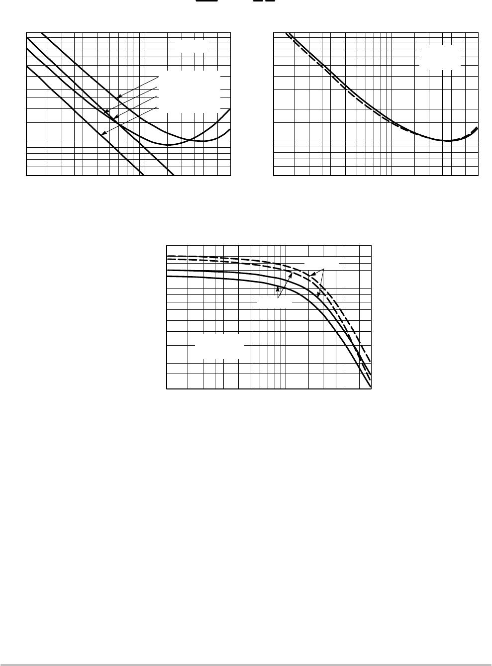
h PARAMETERS
V
CE
= −10 Vdc, f = 1.0 kHz, T
A
= 25°C
This group of graphs illustrates the relationship between
h
fe
and other “h” parameters for this series of transistors. To
obtain these curves, a high−gain and a low−gain unit were
selected from the 2N4402 line, and the same units were used
to develop the correspondingly−numbered curves on each
graph.
Figure 10. Current Gain
I
C
, COLLECTOR CURRENT (mAdc)
0.1 0.2 0.5 0.7 1.0
2.0 3.0 10
0.3
300
700
30
200
100
1000
h
fe
, CURRENT GAIN
h
ie
, INPUT IMPEDANCE (OHMS)
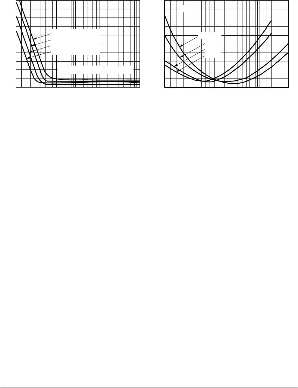
Figure 11. Input Impedance
I
C
, COLLECTOR CURRENT (mAdc)
100k
100
50
5.0 7.0
20k
10k
5k
2k
1k
0.1 0.2 0.5 0.7 1.0
2.0 3.0 10
0.3
5.0 7.0
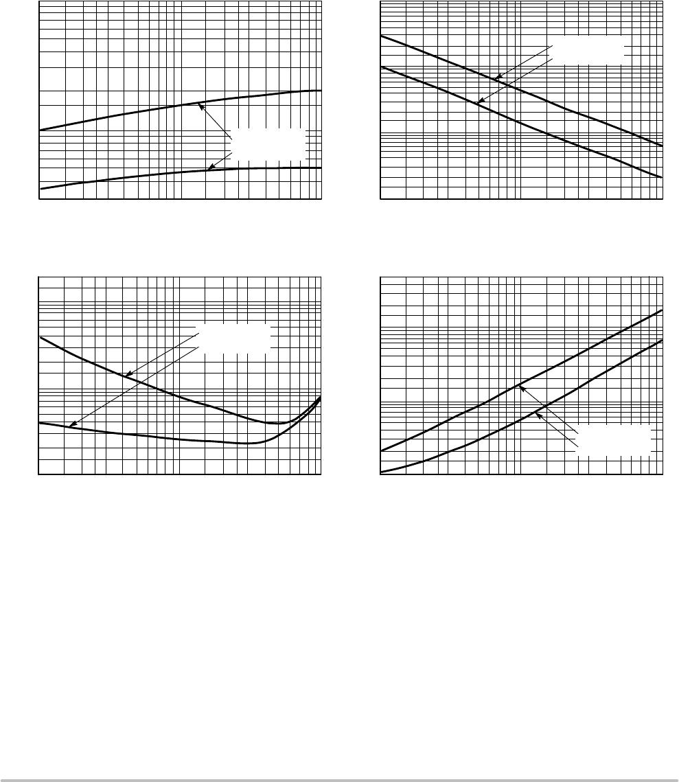
Figure 12. Voltage Feedback Ratio
I
C
, COLLECTOR CURRENT (mAdc)
0.1 0.2 0.5 0.7 1.0
2.0 3.0 10
0.3
0.1
20
Figure 13. Output Admittance
I
C
, COLLECTOR CURRENT (mAdc)
500
1.0
5.0 7.0
50
20
10
5.0
2.0
5.0
2.0
1.0
0.5
0.2
h , OUTPUT ADMITTANCE ( mhos)
oe
h , VOLTAGE FEEDBACK RATIO (X 10 )
re
m
−4
2N4402 UNIT 1
2N4402 UNIT 2
0.1 0.2 0.5 0.7 1.0
2.0 3.0 10
0.3
5.0 7.0
500
70
50k
500
200
2N4402 UNIT 1
2N4402 UNIT 2
2N4402 UNIT 1
2N4402 UNIT 2
10
2N4402 UNIT 1
2N4402 UNIT 2
100