© Semiconductor Components Industries, LLC, 2016
November, 2016 − Rev. 21
1 Publication Order Number:
NCV8402/D
NCV8402, NCV8402A
Self-Protected Low Side
Driver with Temperature
and Current Limit
NCV8402/A is a three terminal protected Low−Side Smart Discrete
device. The protection features include overcurrent, overtemperature,
ESD and integrated Drain−to−Gate clamping for overvoltage
protection. This device offers protection and is suitable for harsh
automotive environments.
Features
• Short−Circuit Protection
• Thermal Shutdown with Automatic Restart
• Overvoltage Protection
• Integrated Clamp for Inductive Switching
• ESD Protection
• NCV8402AMNWT1G − Wettable Flanks Product
• dV/dt Robustness
• Analog Drive Capability (Logic Level Input)
• NCV Prefix for Automotive and Other Applications Requiring
Unique Site and Control Change Requirements; AEC−Q100
Qualified and PPAP Capable
• These Devices are Pb−Free and are RoHS Compliant
Typical Applications
• Switch a Variety of Resistive, Inductive and Capacitive Loads
• Can Replace Electromechanical Relays and Discrete Circuits
• Automotive / Industrial
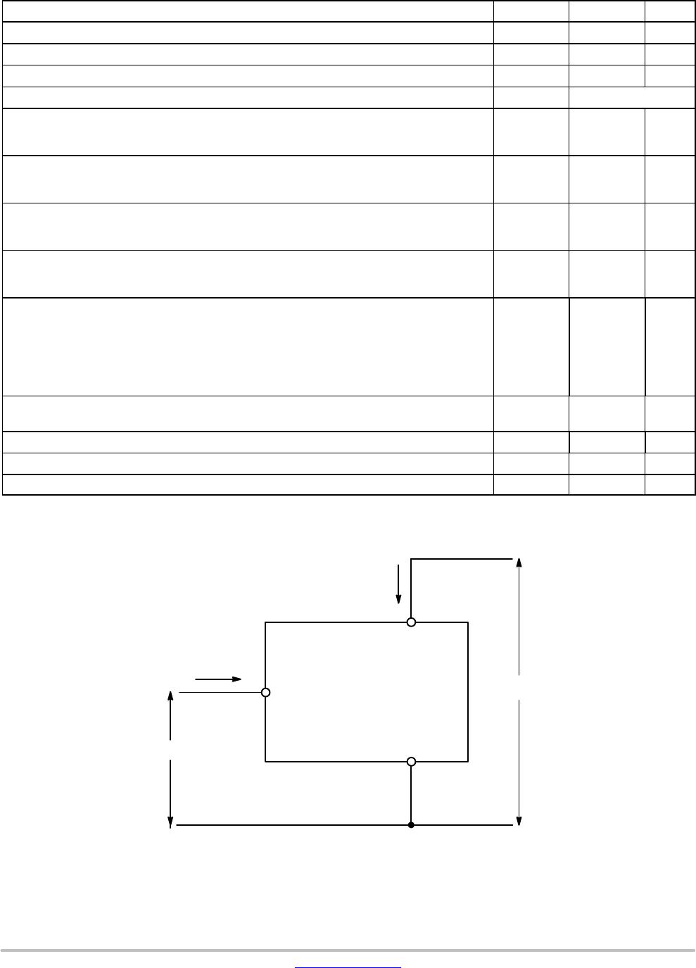
Drain
Source
Temperature
Limit
Gate
Input
Current
Limit
Current
Sense
Overvoltage
Protection
ESD Protection
www.onsemi.com
*Max current limit value is dependent on input
condition.
SOT−223
CASE 318E
STYLE 3
MARKING DIAGRAMS
V
(BR)DSS
(Clamped)
R
DS(ON)
TYP
I
D
MAX
42 V
165 mW @ 10 V
2.0 A*
A = Assembly Location
Y = Year
W or WW = Work Week
xxxxx = V8402 or 8402A
G = Pb−Free Package
1
(Note: Microdot may be in either location)
1
AYW
xxxxx G
G
23
4
GATE
DRAIN
SOURCE
DRAIN
2
3
4
DFN6
CASE 506AX
xxxxx
AYWW
G
1
See detailed ordering and shipping information on page 11 o
this data sheet.
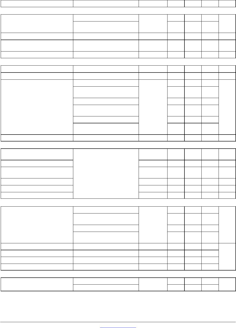
ORDERING INFORMATION
DFN6 PACKAGE PIN DESCRIPTION
*Pins 4, 5, 6 are internally shorted together.
It is recommended to short these pins externally.
GNCNC
7
EPAD
SSS
123
654
Pin # Symbol Description
1 G Gate Input
2 NC No Connect
3 NC No Connect
4 S* Source
5 S* Source
6 S* Source
7 EPAD Drain
1
1
DFN6 (WF)
CASE 506DK
xxxxx
AYWW
G
1