NLU3G17
www.onsemi.com
4
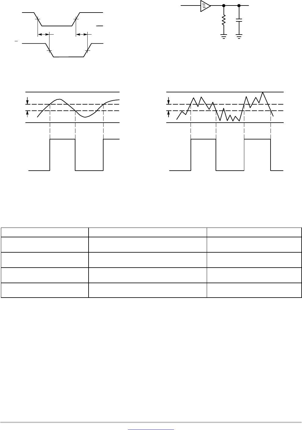
Figure 3. Switching Waveforms
Figure 4. Test Circuit
A 1−MHz square input wave is recommended for propagation delay tests.
C
L
INPUT
OUTPUT
R
L
V
CC
GND
50%
50% V
CC
A or B
Y
t
PHL
t
PLH
Figure 5. Typical Schmitt−Trigger Applications
V
H
V
IN
V
out
CC
V
T+
V
T−
GND
V
OH
V
OL
V
H
V
IN
V
OUT
CC
V
T+
V
T−
GND
V
OH
V
OL
(a) A Schmitt−Trigger Squares Up Inputs With Slow Rise and Fall Times (b) A Schmitt−Trigger Offers Maximum Noise Immunity
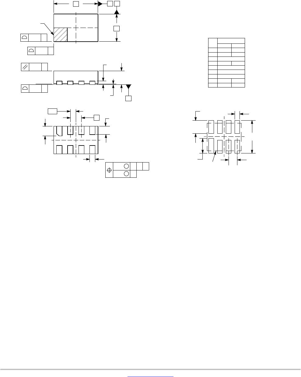
ORDERING INFORMATION
Device Package Shipping
†
NLU3G17MUTAG UDFN8
(Pb−Free)
3000 / Tape & Reel
NLU3G17DMUTCG UDFN8, 1.95 x 1.0, 0.5P
(Pb−Free)
3000 / Tape & Reel
NLU3G17EMUTCG UDFN8, 1.6 x 1.0, 0.4P
(Pb−Free)
3000 / Tape & Reel
NLU3G17FMUTCG UDFN8, 1.45 x 1.0, 0.35P
(Pb−Free)
3000 / Tape & Reel
†For information on tape and reel specifications, including part orientation and tape sizes, please refer to our Tape and Reel Packaging
Specifications Brochure, BRD8011/D.