TC74VCX157FT/FK
2014-03-01 8
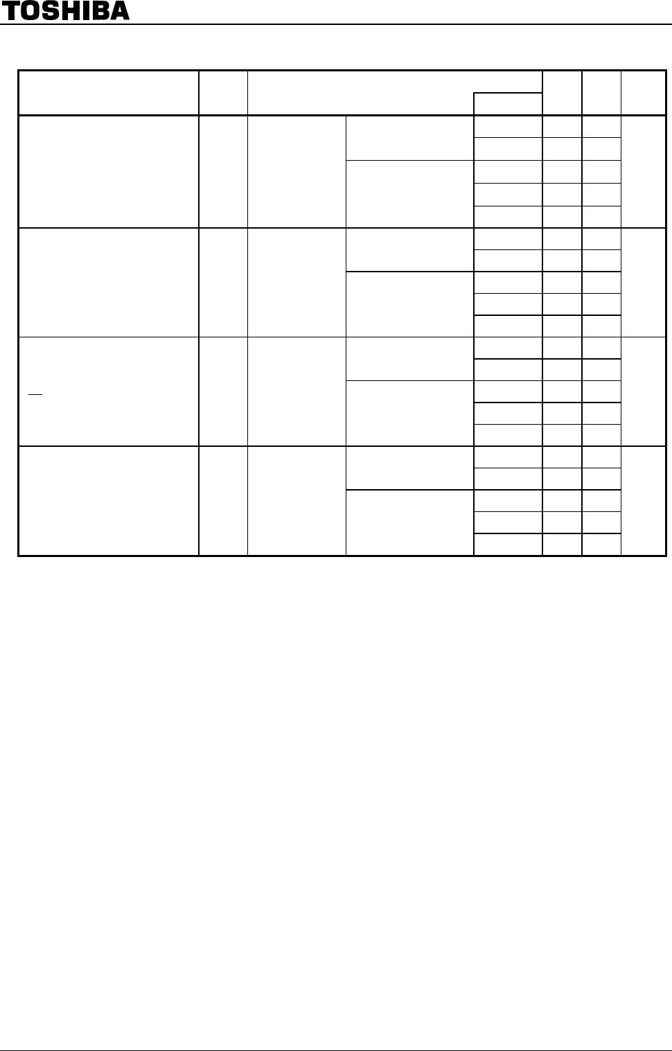
Dynamic Switching Characteristics
(Ta
=
25°C, Input: t
r
=
t
f
=
2.0 ns, C
L
=
30 pF)
Characteristics Symbol Test Condition
V
CC
(V)
Typ. Unit
V
IH
= 1.8 V, V
IL
= 0 V (Note) 1.8 0.25
V
IH
= 2.5 V, V
IL
= 0 V (Note) 2.5 0.6
Quiet output maximum dynamic V
OL
V
OLP
V
IH
= 3.3 V, V
IL
= 0 V (Note) 3.3 0.8
V
V
IH
= 1.8 V, V
IL
= 0 V (Note) 1.8 −0.25
V
IH
= 2.5 V, V
IL
= 0 V (Note) 2.5 −0.6
Quiet output minimum dynamic V
OL
V
OLV
V
IH
= 3.3 V, V
IL
= 0 V (Note) 3.3 −0.8
V
V
IH
= 1.8 V, V
IL
= 0 V (Note) 1.8 1.5
V
IH
= 2.5 V, V
IL
= 0 V (Note) 2.5 1.9
Quiet output minimum dynamic V
OH
V
OHV
V
IH
= 3.3 V, V
IL
= 0 V (Note) 3.3 2.2
V
Note: This parameter is guaranteed by design.
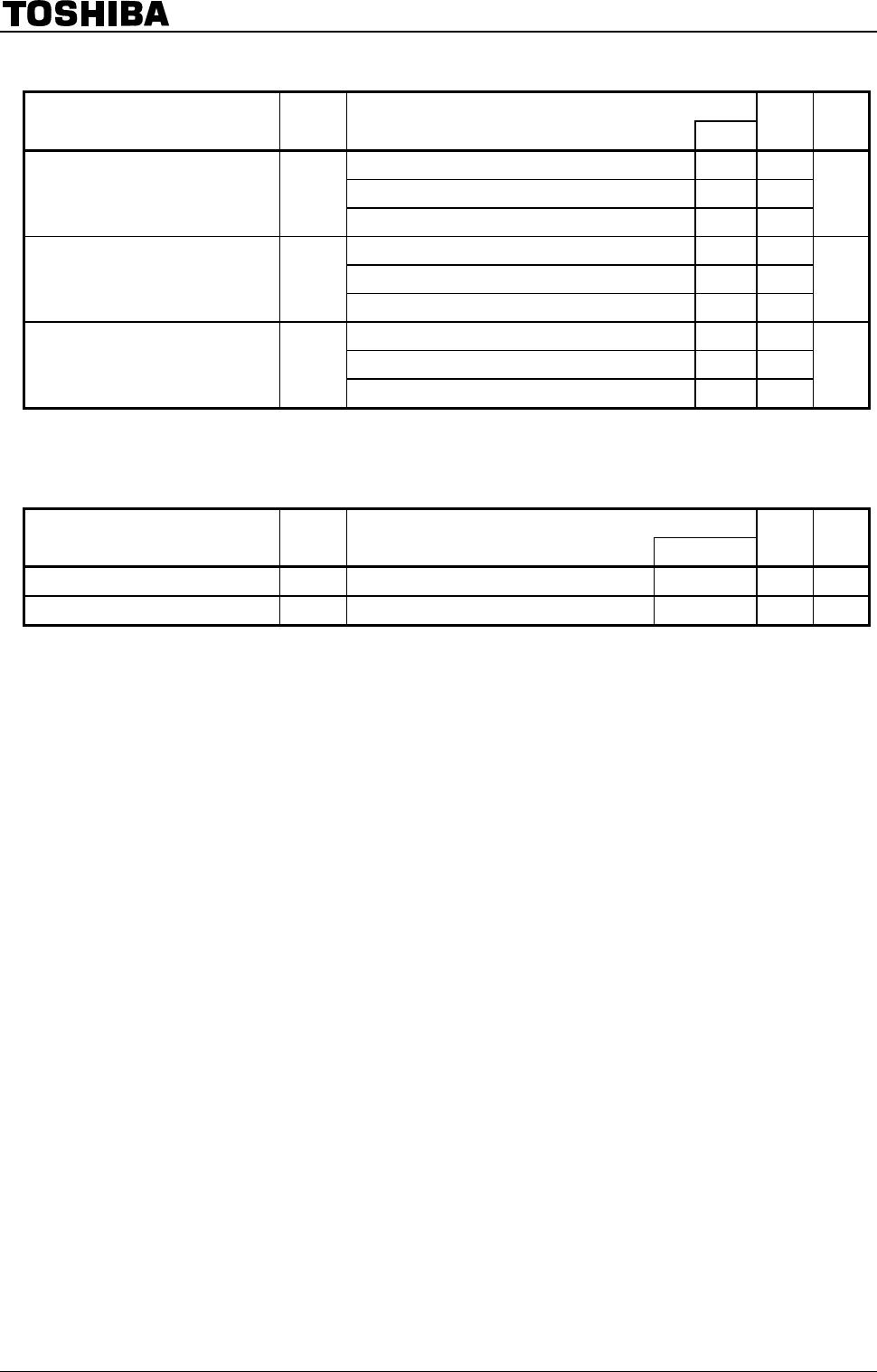
Capacitive Characteristics
(Ta
=
25°C)
Characteristics Symbol Test Condition
V
CC
(V)
Typ. Unit
Input capacitance
C
IN
⎯ 1.8, 2.5, 3.3 6 pF
Power dissipation capacitance C
PD
f
IN
= 10 MHz (Note) 1.8, 2.5, 3.3 20 pF
Note: C
PD
is defined as the value of the internal equivalent capacitance which is calculated from the operating
current consumption without load.
Average operating current can be obtained by the equation:
I
CC (opr)
= C
PD
・V
CC
・f
IN
+ I
CC