ISL9000A
4
FN6391.3
October 15, 2015
Submit Document Feedback
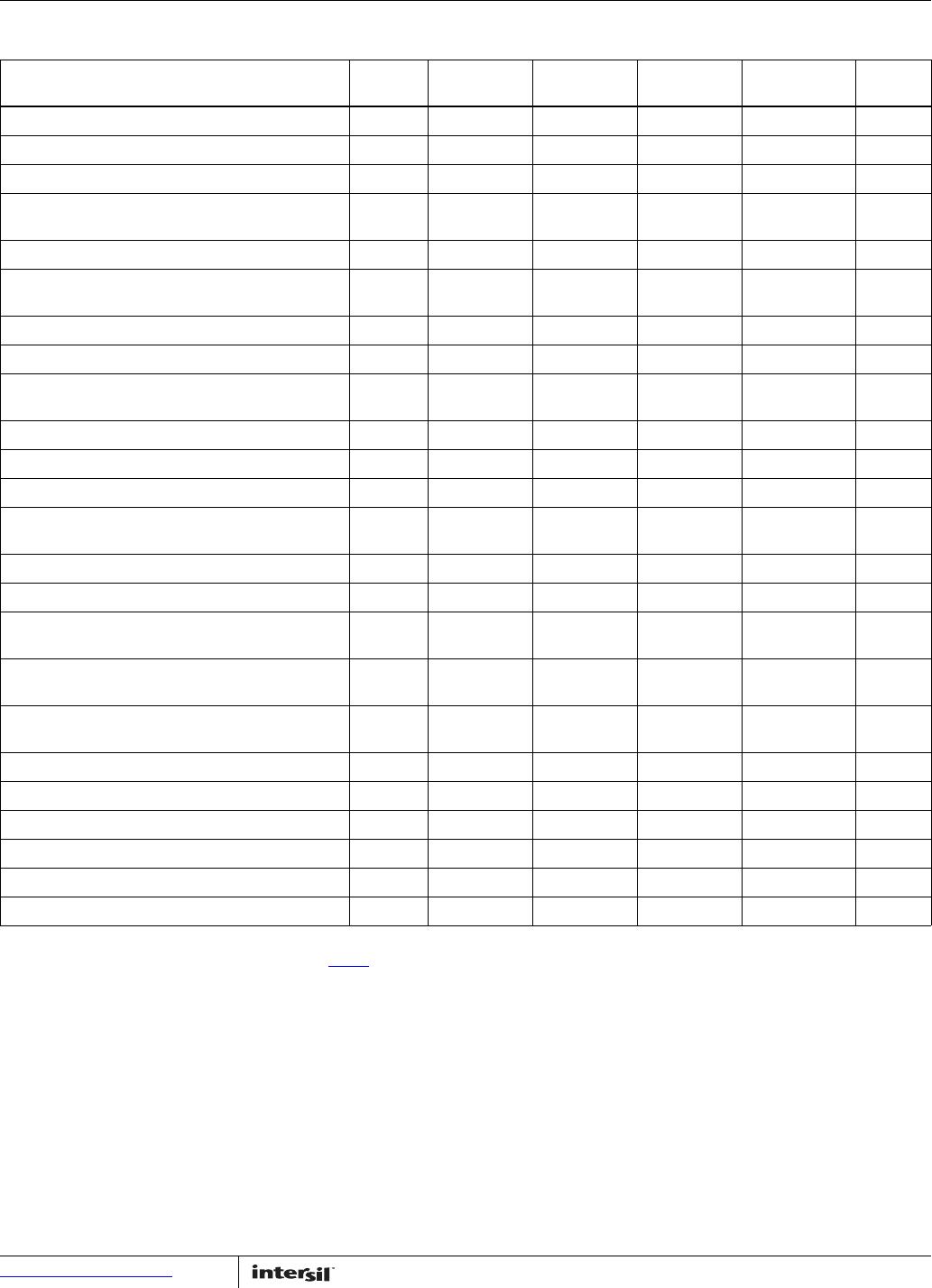
Ordering Information
PART NUMBER
(Notes 1, 3)
PART
MARKING
VO1 VOLTAGE
(V) (Note 2)
VO2 VOLTAGE
(V) (Note 2)
TEMP RANGE
(°C)
PACKAGE
(Pb-Free)
PKG
DWG. #
ISL9000AIRNNZ DEYA 3.3 3.3 -40 to +85 10 Ld 3x3 DFN L10.3x3C
ISL9000AIRNJZ DEWA 3.3 2.8 -40 to +85 10 Ld 3x3 DFN L10.3x3C
ISL9000AIRNFZ DEVA 3.3 2.5 -40 to +85 10 Ld 3x3 DFN L10.3x3C
ISL9000AIRNCZ (No longer available,
recommended replacement: ISL9000AIRNJZ)
DETA 3.3 1.8 -40 to +85 10 Ld 3x3 DFN L10.3x3C
ISL9000AIRMNZ DESA 3.0 3.3 -40 to +85 10 Ld 3x3 DFN L10.3x3C
ISL9000AIRMMZ (No longer available,
recommended replacement: ISL9000AIRMGZ-T)
DERA 3.0 3.0 -40 to +85 10 Ld 3x3 DFN L10.3x3C
ISL9000AIRMGZ DEPA 3.0 2.7 -40 to +85 10 Ld 3x3 DFN L10.3x3C
ISL9000AIRLLZ DENA 2.9 2.9 -40 to +85 10 Ld 3x3 DFN L10.3x3C
ISL9000AIRKNZ (No longer available,
recommended replacement: ISL9000AIRKCZ-T)
DELA 2.85 3.3 -40 to +85 10 Ld 3x3 DFN L10.3x3C
ISL9000AIRKKZ DEKA 2.85 2.85 -40 to +85 10 Ld 3x3 DFN L10.3x3C
ISL9000AIRKJZ DEJA 2.85 2.8 -40 to +85 10 Ld 3x3 DFN L10.3x3C
ISL9000AIRKFZ DEHA 2.85 2.5 -40 to +85 10 Ld 3x3 DFN L10.3x3C
ISL9000AIRKPZ (No longer available,
recommended replacement: ISL9000AIRKCZ-T)
DEMA 2.85 1.85 -40 to +85 10 Ld 3x3 DFN L10.3x3C
ISL9000AIRKCZ DEGA 2.85 1.8 -40 to +85 10 Ld 3x3 DFN L10.3x3C
ISL9000AIRJNZ DEEA 2.8 3.3 -40 to +85 10 Ld 3x3 DFN L10.3x3C
ISL9000AIRJMZ (No longer available,
recommended replacement: ISL9000AIRJBZ-T)
DEDA 2.8 3.0 -40 to +85 10 Ld 3x3 DFN L10.3x3C
ISL9000AIRJRZ (No longer available,
recommended replacement: ISL9000AIRJNZ-T)
DEFA 2.8 2.6 -40 to +85 10 Ld 3x3 DFN L10.3x3C
ISL9000AIRJCZ (No longer available,
recommended replacement: ISL9000AIRJBZ-T)
DECA 2.8 1.8 -40 to +85 10 Ld 3x3 DFN L10.3x3C
ISL9000AIRJBZ DEBA 2.8 1.5 -40 to +85 10 Ld 3x3 DFN L10.3x3C
ISL9000AIRFJZ DDVA 2.5 2.8 -40 to +85 10 Ld 3x3 DFN L10.3x3C
ISL9000AIRFDZ DDTA 2.5 2.0 -40 to +85 10 Ld 3x3 DFN L10.3x3C
ISL9000AIRFCZ DDSA 2.5 1.8 -40 to +85 10 Ld 3x3 DFN L10.3x3C
ISL9000AIRCJZ DDRA 1.8 2.8 -40 to +85 10 Ld 3x3 DFN L10.3x3C
ISL9000AIRCCZ DDPA 1.8 1.8 -40 to +85 10 Ld 3x3 DFN L10.3x3C
NOTES:
1. Add “-T*” suffix for tape and reel. Please refer to TB347
for details on reel specifications.
2. For other output voltages, contact Intersil Marketing.
3. These Intersil Pb-free plastic packaged products employ special Pb-free material sets, molding compounds/die attach materials, and 100% matte
tin plate plus anneal (e3 termination finish, which is RoHS compliant and compatible with both SnPb and Pb-free soldering operations). Intersil
Pb-free products are MSL classified at Pb-free peak reflow temperatures that meet or exceed the Pb-free requirements of IPC/JEDEC J STD-020.

