3
ECL Pro™
SY10EP05V
Micrel, Inc.
M9999-112805
hbwhelp@micrel.com or (408) 955-1690
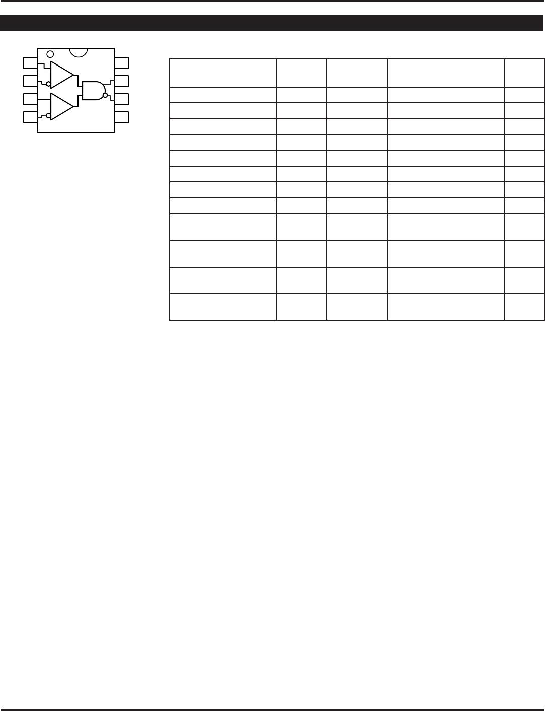
Symbol Rating Value Unit
V
CC
—V
EE
Power Supply Voltage 6V V
V
IN
Input Voltage (V
CC
= 0V, V
I
not more negative than V
EE
) –6.0 to 0 V
Input Voltage (V
EE
= 0V, V
I
not more positive than V
CC
) +6.0 to 0 V
I
OUT
Output Current –Continuous 50 mA
–Surge 100
T
LEAD
Lead Temperature +260 °C
T
A
Operating Temperature Range –40 to +85 °C
T
store
Storage Temperature Range –65 to +150 °C
θ
JA
Package Thermal Resistance –Still-Air (SOIC) 160 °C/W
(Junction-to-Ambient) –500lfpm (SOIC) 109
–Still-Air (MSOP) 206 °C/W
–500lfpm (MSOP) 155
θ
JC
Package Thermal Resistance (SOIC) 39 °C/W
(Junction-to-Case) (MSOP) 39
Note 1. Permanent device damage may occur if absolute maximum ratings are exceeded. This is a stress rating only and functional operation is not
implied at conditions other than those detailed in the operational sections of this data sheet. Exposure to absolute maximum ratlng conditions
for extended periods may affect device reliability.
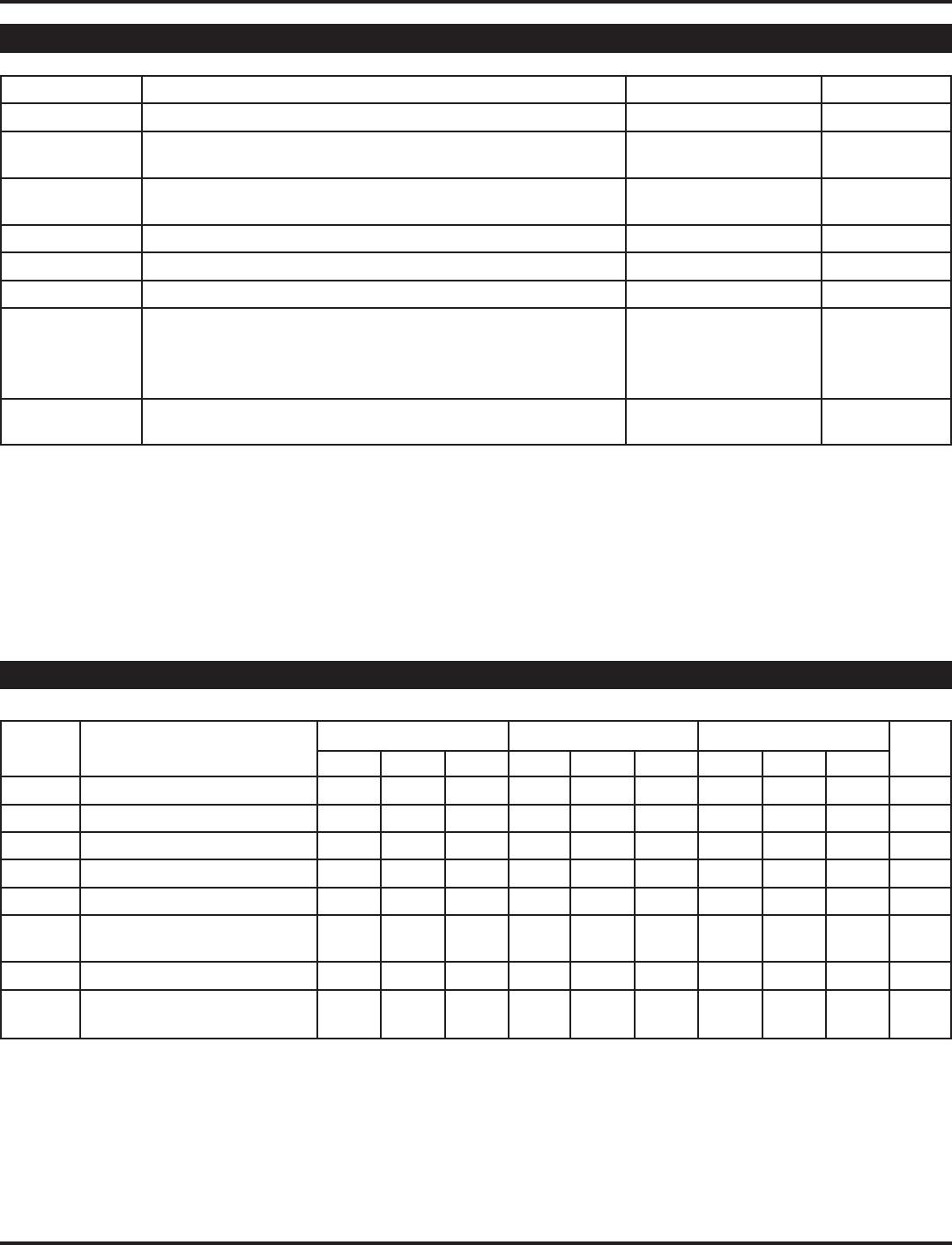
ABSOLUTE MAXIMUM RATINGS
(1)
T
A
= –40°CT
A
= +25°CT
A
= +85°C
Symbol Parameter Min. Typ. Max. Min. Typ. Max. Min. Typ. Max. Unit
I
EE
Power Supply Current
(3)
— 22 29 — 24 29 — 22 29 mA
V
OH
Output HIGH Voltage
(4)
3865 3940 4115 3930 4055 4180 3990 4115 4240 mV
V
OL
Outuput LOW Voltage
(4)
3050 3190 3315 3050 3255 3380 3050 3315 3440 mV
V
IH
Input HIGH Voltage 3790 — 4115 3855 — 4180 3915 — 4240 mV
V
IL
Input LOW Voltage 3065 — 3390 3130 — 3455 3190 — 3515 mV
V
IHCMR
Input HIGH Voltage
2.0 — V
CC
2.0 — V
CC
2.0 — V
CC
V
Common Mode Range
I
IH
Input HIGH Current — — 150 — — 150 — — 150 µA
I
IL
Input LOW Current D 0.5 — — 0.5 — — 0.5 — — µA
/D –150 — — –150 — — –150 — —
Note 1. 10EP circuits are designed to meet the DC specifications shown in the above table after thermal equilibrium has been established. The circuit
is in a test socket or mounted on a printed circuit board and traverse airflow greater than 500lfpm is maintained.
Note 2. Input and output parameters vary 1:1 with V
CC
.
Note 3. V
CC
= 0V, V
EE
= V
EE
(min) to V
EE
(max), all other pins floating.
Note 4. All loading with 50Ω to V
CC
–2.0V.
PECL DC ELECTRICAL CHARACTERISTICS
(1)
V
CC
= 4.5V to 5.5V; V
EE
= 0V
(2)