4
ECL Pro™
SY10EP05V
Micrel, Inc.
M9999-112805
hbwhelp@micrel.com or (408) 955-1690
T
A
= –40°CT
A
= +25°CT
A
= +85°C
Symbol Parameter Min. Typ. Max. Min. Typ. Max. Min. Typ. Max. Unit
I
EE
Power Supply Current
(3)
— 22 29 — 22 29 — 24 29 mA
V
OH
Output HIGH Voltage
(4)
2165 2240 2415 2230 2355 2480 2290 2415 2540 mV
V
OL
Outuput LOW Voltage
(4)
1350 1490 1615 1350 1555 1680 1350 1615 1740 mV
V
IH
Input HIGH Voltage 2090 — 2415 2155 — 2480 2215 — 2540 mV
V
IL
Input LOW Voltage 1365 — 1690 1430 — 1755 1490 — 1815 mV
V
IHCMR
Input HIGH Voltage
2.0 — V
CC
2.0 — V
CC
2.0 — V
CC
V
Common Mode Range
I
IH
Input HIGH Current — — 150 — — 150 — — 150 µA
I
IL
Input LOW Current D 0.5 — — 0.5 — — 0.5 — — µA
/D –150 — — –150 — — –150 — —
Note 1. 10EP circuits are designed to meet the DC specifications shown in the above table after thermal equilibrium has been established. The circuit
is in a test socket or mounted on a printed circuit board and traverse airflow greater than 500lfpm is maintained.
Note 2. Input and output parameters vary 1:1 with V
CC
.
Note 3. V
CC
= 0V, V
EE
= V
EE
(Min) to V
EE
(Max), all other pins floating.
Note 4. All loading with 50Ω to V
CC
–2.0V.
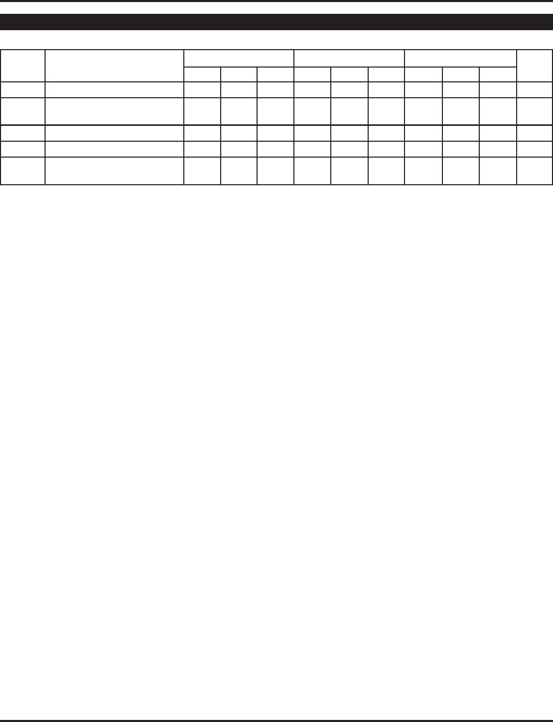
LVPECL DC ELECTRICAL CHARACTERISTICS
(1)
V
CC
= 3.0V to 3.6V; V
EE
= 0V
(2)
T
A
= –40°CT
A
= +25°CT
A
= +85°C
Symbol Parameter Min. Typ. Max. Min. Typ. Max. Min. Typ. Max. Unit
I
EE
Power Supply Current
(3)
— 22 29 — 22 29 — 22 29 mA
V
OH
Output HIGH Voltage
(4)
–1135 –1060 –885 –1070 –945 –820 –1010 –885 –760 mV
V
OL
Outuput LOW Voltage
(4)
–1950 –1810 –1685 –1950 –1745 –1620 –1950 –1685 –1560 mV
V
IH
Input HIGH Voltage –1210 — –885 –1145 — –820 –1085 — –760 mV
V
IL
Input LOW Voltage –1935 — –1610 –1870 — –1545 –1810 — –1485 mV
V
IHCMR
Input HIGH Voltage
V
EE
+2.0 V
CC
V
EE
+2.0 V
CC
V
EE
+2.0 V
CC
V
Common Mode Range
I
IH
Input HIGH Current — — 150 — — 150 — — 150 µA
I
IL
Input LOW Current D 0.5 — — 0.5 — — 0.5 — — µA
/D –150 — — –150 — — –150 — —
Note 1. 10EP circuits are designed to meet the DC specifications shown in the above table after thermal equilibrium has been established. The circuit
is in a test socket or mounted on a printed circuit board and traverse airflow greater than 500lfpm is maintained.
Note 2. Input and output parameters vary 1:1 with V
CC
.
Note 3. V
CC
= 0V, V
EE
= V
EE
(min) to V
EE
(max), all other pins floating.
Note 4. All loading with 50Ω to V
CC
–2.0V.
ECL/LVECL DC ELECTRICAL CHARACTERISTICS
(1)
V
CC
= 0V, V
EE
= –5.5V to –3.0V
(2)