LTC4231
11
4321fa
For more information www.linear.com/LTC4231
applicaTions inForMaTion
In most applications, keeping the inrush current at ana-
log current limit is an acceptable start-up method if the
TIMER
delay is long enough to avoid setting the current
fault latch and the MOSFET has adequate safe operating
margin. However, for more flexibility in design (See the
Design Example section), a capacitor from GATE to GND
(Figure 1) can be used to limit the V
GATE
slew rate for inrush
current control. V
GATE
rises with a slope equal to 10μA/C
G
(Figure 3). The supply inrush current is then limited to:
I
INRUSH
=
L
C
G
• 10µA
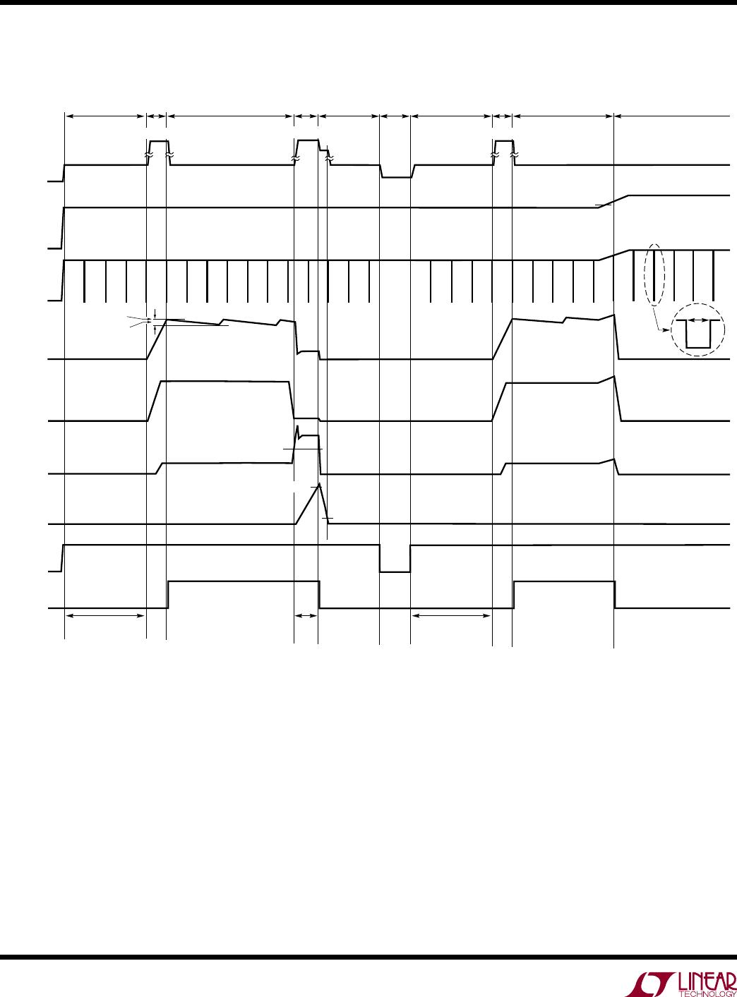
Once ∆V
GATE
exceeds ∆V
GATE(H)
, STATUS goes high imped-
ance. I
CC
drops from 300µA to 4µA (average) during this
normal on mode as some circuit blocks are shut down
and the internal charge pump periodically turns on when
∆V
GATE
droops by 0.7V or every 15ms, whichever comes
first (Figure 7).
In the back-to-back MOSFET configuration as shown in
Figure 5, SOURCE will also be pulled to GND via the para-
sitic body
diode between GATE and SOURCE, cutting off
the
load from IN. This configuration is suitable in power
path control and reverse battery protection applications
where IN is likely to go below GND.
In the single MOSFET configuration (Figure 1), the 1mA
pull-down from GATE to GND also discharges the load
capacitor C
L
to GND once GATE goes below SOURCE.
Overcurrent Fault
The 50mV circuit breaker threshold sets the maximum load
current allowed under steady state conditions. However,
the LTC4231 allows mild overcurrents during supply or
load transients when ∆V
SENSE
momentarily exceeds 50mV
but stays below the 80mV analog current limit threshold.
For severe overcurrents when ∆V
SENSE
exceeds 80mV,
the analog current limit amplifier controls ∆V
GATE
to regu-
late
∆V
SENSE
to 80mV. The durations of these transient
overcurrents must be less than the circuit breaker delay
(t
CB
) which can be adjusted using the capacitor C
T
at the
TIMER pin.
When ∆V
SENSE
exceeds 50mV, the LTC4231 goes into
overcurrent mode. C
T
is charged with a 50μA pull-up. If
the overcurrent is transient and ∆V
SENSE
goes below 50mV
before TIMER reaches 1.193V, the 50μA pull-up on TIMER
switches to a 5μA pull-down. Multiple overcurrents with
a duty cycle > 10% can thus eventually integrate TIMER
to 1.193V. When TIMER reaches 1.193V, the LTC4231
goes into current fault mode and sets an internal current
fault latch. The external MOSFET will be cut off by a 1mA
pull-down from GATE to GND while STATUS pull-down
is asserted.
The time in which LTC4231 stays in overcurrent mode
before going into current fault mode is called the circuit
breaker delay and is given by:
t
CB
= C
T
• 24 [ms/µF]
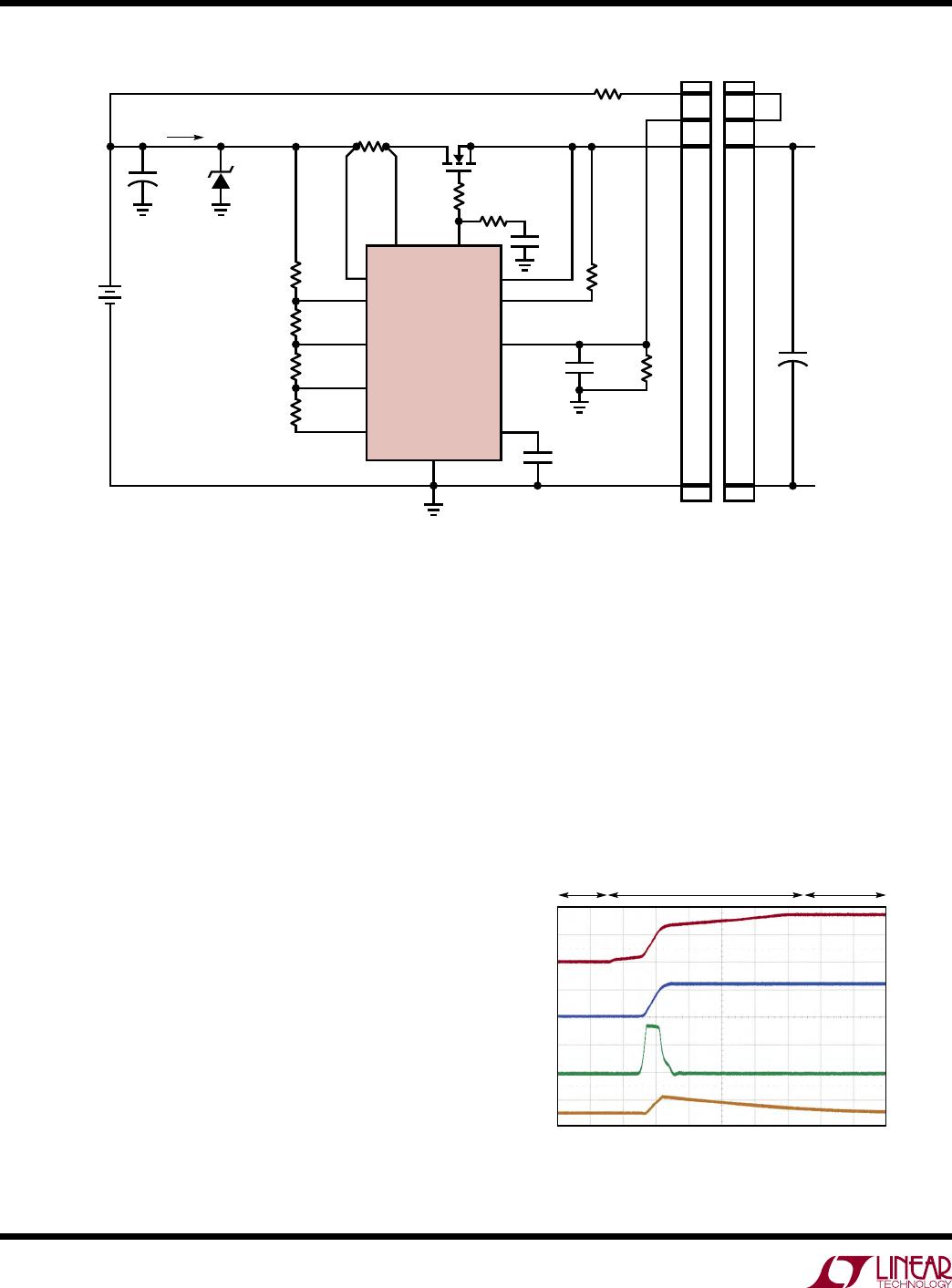
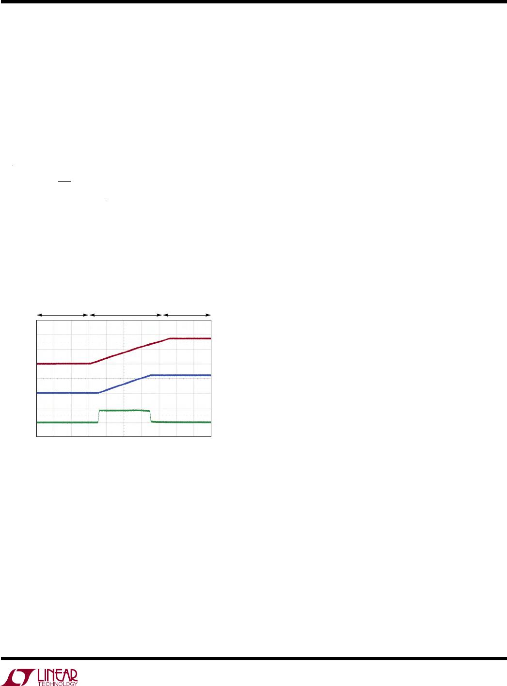
Figure 3. Inrush Control by Limiting V
GATE
Slew
GATE
20V/DIV
OUT
20V/DIV
I
LOAD
0.5A/DIV
20ms/DIV
4231 F03
START-UP NORMAL ON
DEBOUNCE
Turn-Off Sequence
The MOSFET switch can be turned off by SHDN going low,
an OV/UV event, an overcurrent setting the current fault
latch or IN dropping below its UVLO voltage. Under any
of these conditions, STATUS pulls low and the MOSFET
is turned off with a 1mA current pulling down from GATE
to GND.