ADuM110N Data Sheet
Rev. 0 | Page 6 of 16
Parameter Symbol Min Typ Max Unit Test Conditions/Comments
Undervoltage Lockout
Positive V
DDx
Threshold V
DDxUV+
1.6 V
Negative V
DDx
Threshold V
DDxUV−
1.5 V
V
DDx
Hysteresis V
DDxUVH
0.1 V
AC SPECIFICATIONS
Output Rise/Fall Time t
R
/t
F
2.5 ns 10% to 90%
Common-Mode Transient Immunity
2
|CM
H
| 75 100 kV/µs
V
I
= V
DD1
, V
CM
= 1000 V,
transient magnitude = 800 V
|CM
L
| 75 100 kV/µs
V
I
= 0 V, V
CM
= 1000 V,
transient magnitude = 800 V
1
N0 indicates the ADuM110N0 models and N1 indicates the ADuM110N1 models. See the Ordering Guide section.
2
|CM
H
| is the maximum common-mode voltage slew rate that can be sustained while maintaining the voltage output (V
O
) > 0.8 V
DD2
. |CM
L
| is the maximum common-
mode voltage slew rate that can be sustained while maintaining V
O
> 0.8 V. The common-mode voltage slew rates apply to both rising and falling common-mode
voltage edges.
Table 6. Total Supply Current vs. Data Throughput—2.5 V Operation
1 Mbps 25 Mbps 100 Mbps
Parameter Symbol Min Typ Max Min Typ Max Min Typ Max Unit
SUPPLY CURRENT
Supply Current Side 1 I
DD1
2.2 3.4 2.4 3.6 3.2 4.3 mA
Supply Current Side 2 I
DD2
0.9 1.4 1.3 1.8 2.3 3.5 mA
ELECTRICAL CHARACTERISTICS—1.8 V OPERATION
All typical specifications are at T
A
= 25°C, V
DD1
= V
DD2
= 1.8 V. Minimum/maximum specifications apply over the entire recommended
operation range: 1.7 V ≤ V
DD1
≤ 1.9 V, 1.7 V ≤ V
DD2
≤ 1.9 V, and −40°C ≤ T
A
≤ +125°C, unless otherwise noted. Switching specifications
are tested with C
L
= 15 pF and CMOS signal levels, unless otherwise noted. Supply currents are specified with 50% duty cycle signals.
Table 7.
Parameter Symbol Min Typ Max Unit Test Conditions/Comments
SWITCHING SPECIFICATIONS
Pulse Width PW 6.6 ns Within PWD limit
Data Rate 150 Mbps Within PWD limit
Propagation Delay t
PHL
, t
PLH
5.8 8.7 15 ns 50% input to 50% output
Pulse Width Distortion PWD 0.7 3 ns |t
PLH
− t
PHL
|
Change vs. Temperature 1.5 ps/°C
Propagation Delay Skew t
PSK
7.0 ns
Between any two units at the same
temperature, voltage, and load
Jitter 630 ps p-p See the Jitter Measurement section
190 ps rms See the Jitter Measurement section
DC SPECIFICATIONS
Input Threshold
Logic High V
IH
0.7 × V
DD1
V
Logic Low V
IL
0.3 × V
DD1
V
Output Voltage
Logic High V
OH
V
DD2
− 0.1 V
DD2
V I
O
= −20 µA, V
I
= V
IH
V
DD2
− 0.4 V
DD2
− 0.2 V I
O
= −2 mA, V
I
= V
IH
Logic Low V
OL
0.0 0.1 V I
O
= 20 µA, V
I
= V
IL
0.2 0.4 V I
O
= 2 mA, V
I
= V
IL
Input Current per Channel I
I
−10 +0.01 +10 µA 0 V ≤ V
I
≤ V
DD1
Quiescent Supply Current
I
DD1 (Q)
0.7 1.1 mA V
I
= 0 (N0), 1 (N1)
1
I
DD2 (Q)
0.9 1.2 mA V
I
= 0 (N0), 1 (N1)
1
I
DD1 (Q)
3.4 5.4 mA V
I
= 1 (N0), 0 (N1)
1
I
DD2 (Q)
0.9 1.2 mA V
I
= 1 (N0), 0 (N1)
1
Data Sheet ADuM110N
Rev. 0 | Page 7 of 16
Parameter Symbol Min Typ Max Unit Test Conditions/Comments
Dynamic Supply Current
Dynamic Input I
DDI (D)
0.01 mA/Mbps Inputs switching, 50% duty cycle
Dynamic Output I
DDO (D)
0.01 mA/Mbps Inputs switching, 50% duty cycle
Undervoltage Lockout UVLO
Positive V
DDx
Threshold V
DDxUV+
1.6 V
Negative V
DDx
Threshold V
DDxUV−
1.5 V
V
DDx
Hysteresis V
DDxUVH
0.1 V
AC SPECIFICATIONS
Output Rise/Fall Time t
R
/t
F
2.5 ns 10% to 90%
Common-Mode Transient Immunity
2
|CM
H
| 75 100 kV/µs
V
I
= V
DD1
, V
CM
= 1000 V, transient
magnitude = 800 V
|CM
L
| 75 100 kV/µs
V
1
= 0 V, V
CM
= 1000 V, transient
magnitude = 800 V
1
N0 indicates the ADuM110N0 models and N1 indicates the ADuM110N1 models. See the Ordering Guide section.
2
|CM
H
| is the maximum common-mode voltage slew rate that can be sustained while maintaining the voltage output (V
O
) > 0.8 V
DD2
. |CM
L
| is the maximum common-
mode voltage slew rate that can be sustained while maintaining V
O
> 0.8 V. The common-mode voltage slew rates apply to both rising and falling common-mode
voltage edges.
Table 8. Total Supply Current vs. Data Throughput—1.8 V Operation
1 Mbps 25 Mbps 100 Mbps
Parameter Symbol Min Typ Max Min Typ Max Min Typ Max Unit
SUPPLY CURRENT
Supply Current Side 1 I
DD1
2.1 3.1 2.3 3.4 3.0 4.2 mA
Supply Current Side 2 I
DD2
0.9 1.2 1.2 1.6 2.2 3.2 mA
INSULATION AND SAFETY RELATED SPECIFICATIONS
For additional information, see www.analog.com/icouplersafety.
Table 9.
Parameter Symbol Value Unit Test Conditions/Comments
Rated Dielectric Insulation Voltage 3000 V rms 1-minute duration
Minimum External Air Gap (Clearance) L (I01) 4.0 mm min
Measured from input terminals to output terminals,
shortest distance through air
Minimum External Tracking (Creepage) L (I02) 4.0 mm min
Measured from input terminals to output terminals,
shortest distance path along body
Minimum Clearance in the Plane of the Printed
Circuit Board (PCB Clearance)
L (PCB) 4.5 mm min
Measured from input terminals to output terminals,
shortest distance through air, line of sight, in the PCB
mounting plane
Minimum Internal Gap (Internal Clearance) 25.5 m min Insulation distance through insulation
Tracking Resistance (Comparative Tracking Index) CTI >400 V DIN IEC 112/VDE 0303 Part 1
Material Group II Material Group (DIN VDE 0110, 1/89, Table 1)
PACKAGE CHARACTERISTICS
Table 10.
Parameter Symbol Min Typ Max Unit Test Conditions/Comments
Resistance (Input to Output)
1
R
I-O
10
13
Capacitance (Input to Output)
1
C
I-O
2 pF f = 1 MHz
Input Capacitance
2
C
I
4.0 pF
IC Junction to Ambient Thermal Resistance θ
JA
80 °C/W Thermocouple located at center of package underside
1
The ADuM110N is considered a 2-terminal device: Pin 1 through Pin 4 are shorted together, and Pin 5 through Pin 8 are shorted together.
2
Input capacitance is from any input data pin to ground.
ADuM110N Data Sheet
Rev. 0 | Page 8 of 16
REGULATORY INFORMATION
See Table 15 and the Insulation Lifetime section for details regarding recommended maximum working voltages for specific cross-
isolation waveforms and insulation levels.
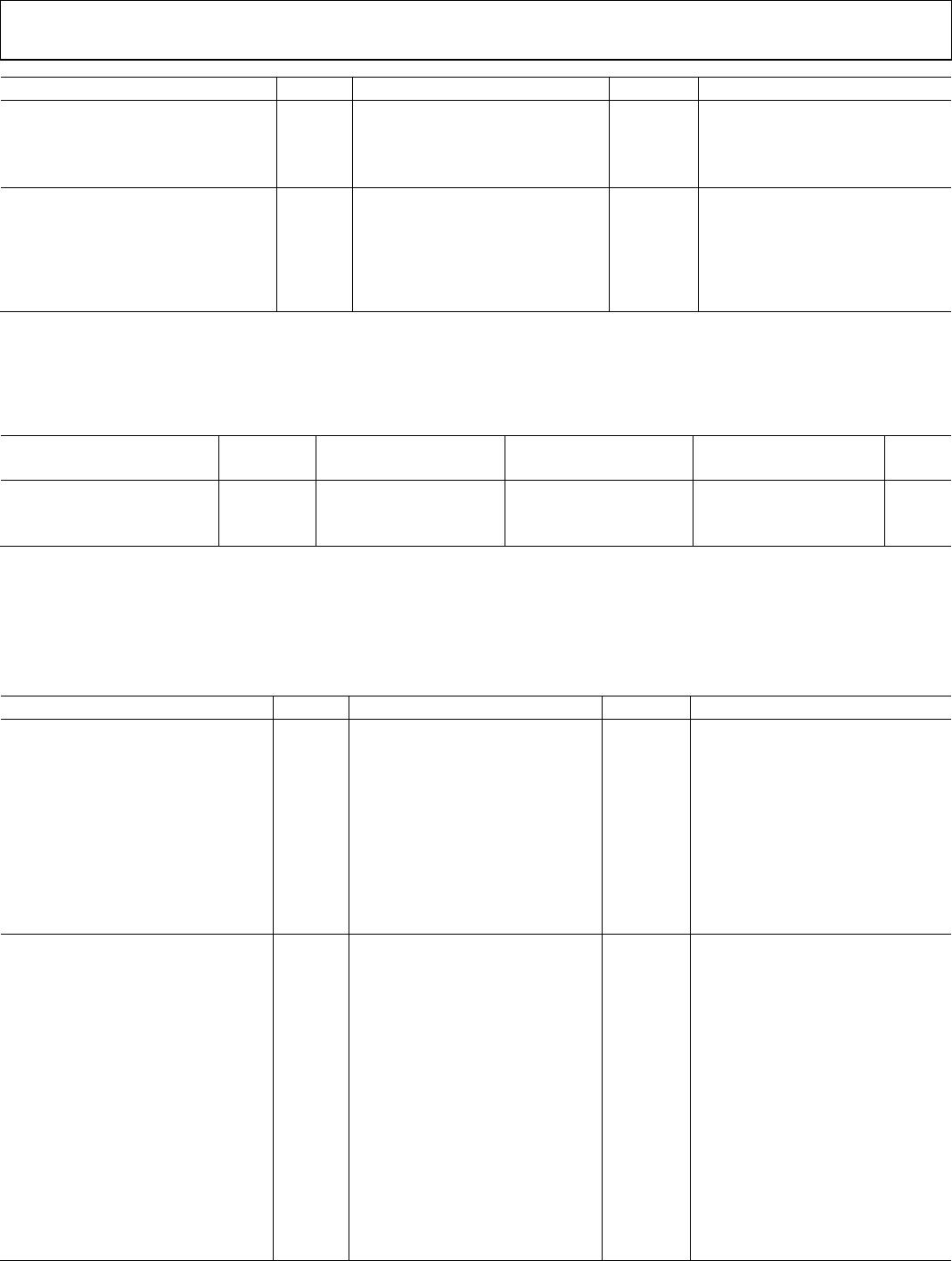
Table 11.
UL (Pending) CSA (Pending) VDE (Pending) CQC (Pending)
Recognized Under 1577
Component Recognition
Program
1
Approved under CSA Component Acceptance
Notice 5A
Certified according to
DIN V VDE V 0884-10 (VDE
V 0884-10):2006-12
2
Certified by
CQC11-471543-2012
Single Protection, 3000 V rms
Isolation Voltage
CSA 60950-1-07+A1+A2 and IEC 60950-1,
Second Edition, +A1+A2
Basic insulation
565 V peak, V
IOSM
=
10 kV peak
GB4943.1-2011
Basic insulation at 400 V rms (565 V peak)
Double Protection, 3000 V rms
Isolation Voltage
Reinforced insulation at 200 V rms (283 V peak)
IEC 60601-1 Edition 3.1
Reinforced insulation,
565 V peak, V
IOSM
=
6000 V peak
Basic insulation at
770 V rms (1089 V peak),
reinforced insulation at
385 V rms (545 V peak),
tropical climate, altitude
≤5000 meters
Basic insulation (1 MOPP), 250 V rms (354 V peak)
CSA 61010-1-12 and IEC 61010-1 Third Edition
Basic insulation at 300 V rms (main),
400 V rms (565 V peak)
Reinforced insulation at 300 V rms (main),
200 V (secondary) (283 V peak)
File E214100 File 205078 File 2471900-4880-0001 File (pending)
1
In accordance with UL 1577, each ADuM110N is proof tested by applying an insulation test voltage ≥ 3600 V rms for 1 sec.
2
In accordance with DIN V VDE V 0884-10, each ADuM110N is proof tested by applying an insulation test voltage ≥ 1059 V peak for 1 sec (partial discharge detection
limit = 5 pC). The * marking branded on the component designates DIN V VDE V 0884-10 approval.
DIN V VDE V 0884-10 (VDE V 0884-10) INSULATION CHARACTERISTICS
This isolator is suitable for reinforced electrical isolation only within the safety limit data. Protective circuits ensure the maintenance of
the safety data. The * marking on packages denotes DIN V VDE V 0884-10 approval.
Table 12.
Description Test Conditions/Comments Symbol Characteristic Unit
Installation Classification per DIN VDE 0110
For Rated Mains Voltage ≤ 150 V rms I to IV
For Rated Mains Voltage ≤ 300 V rms I to III
For Rated Mains Voltage ≤ 400 V rms I to III
Climatic Classification 40/105/21
Pollution Degree per DIN VDE 0110, Table 1 2
Maximum Working Insulation Voltage V
IORM
565 V peak
Input to Output Test Voltage, Method B1
V
IORM
× 1.875 = V
pd (m)
, 100% production test,
t
ini
= t
m
= 1 sec, partial discharge < 5 pC
V
pd (m)
1059 V peak
Input to Output Test Voltage, Method A
After Environmental Tests Subgroup 1
V
IORM
× 1.5 = V
pd (m)
, t
ini
= 60 sec, t
m
= 10 sec,
partial discharge < 5 pC
V
pd (m)
848 V peak
After Input and/or Safety Test Subgroup 2
and Subgroup 3
V
IORM
× 1.2 = V
pd (m)
, t
ini
= 60 sec, t
m
= 10 sec,
partial discharge < 5 pC
678 V peak
Highest Allowable Overvoltage V
IOTM
4200 V peak
Surge Isolation Voltage
Basic
V peak = 10.0 kV, 1.2 µs rise time, 50 µs,
50% fall time
V
IOSM
10,000 V peak
Reinforced
V peak = 10.0 kV, 1.2 µs rise time, 50 µs,
50% fall time
V
IOSM
6000 V peak

ADUM110N1BRZ

Mfr. #:
Manufacturer:
Analog Devices Inc.
Description:
Digital Isolators 2 Channel 3kV Digital Isolator
Lifecycle:
New from this manufacturer.
Delivery:
DHL FedEx Ups TNT EMS
Payment:
T/T Paypal Visa MoneyGram Western Union