General Description
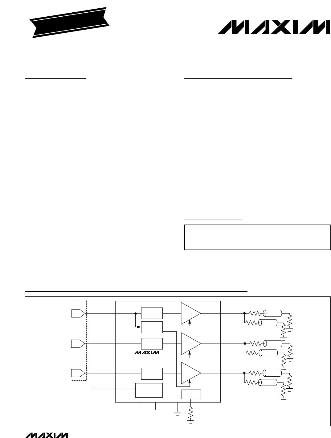
The MAX7438/MAX7439 three-channel standard defini-
tion video reconstruction filters include a back-porch
clamp that sets the output blanking level of the video
signal to ground. Each channel of the MAX7438/
MAX7439 combines a lowpass filter with adjustable
high-frequency boost levels and an output buffer capa-
ble of driving two standard 150 video loads. The
blanking level of the output video signal on each chan-
nel is clamped to ground, eliminating the need for large
AC-coupling output capacitors. Direct input coupling
circuitry eliminates the need for AC-coupling input
capacitors. This DC-in/DC-out architecture results in
extremely low line-time distortion. The MAX7438/
MAX7439 are ideal for antialiasing and DAC smoothing
in digital video devices such as STBs, DVDs, PVRs,
and hard disk recorders. The MAX7438/MAX7439 oper-
ate from ±5V dual supplies.
The three-channel MAX7438/MAX7439 are ideal for Y,
P
b
, P
r
, and RGB component video signals, three com-
posite video signals, and also Y/C plus CVBS video sig-
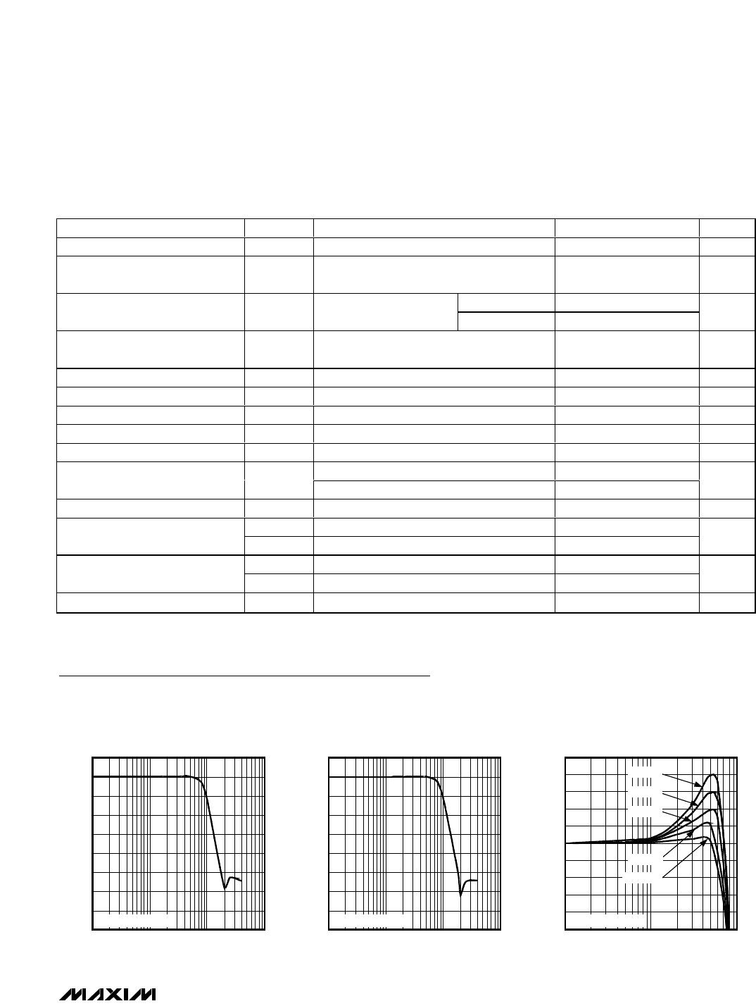
nals. Each filter channel achieves 60dB of attenuation at
27MHz and a maximally flat passband from DC to 5MHz.
The MAX7438 offers an internal gain of +2V/V, while the
MAX7439 offers a gain of +3V/V.
Applications
Features
Back-Porch of Video Output Signal Clamped to
Ground
Eliminates Input/Output AC-Coupling Capacitors
0.1% Line-Time Distortion
Stopband: 55dB at 27MHz
Passband: ±0.8dB out to 5MHz
Diff Gain = 0.05%, Diff Phase = 0.05 Degrees
Output Clamped to Ground with Loss of Input
Each Output Drives Two 150 Video Loads
Up to 2dB of High-Frequency Boost Control
Ideal for CVBS, Y/C (S-Video), and RGB (Y, P
b,
P
r
)
Outputs for NTSC, PAL, and SDTV
Filter Bypass Mode
Small 20-Pin 5mm
5mm Thin QFN Package
MAX7438/MAX7439
Triple-Channel Video Reconstruction Filters with
Back-Porch Clamp to GND
________________________________________________________________ Maxim Integrated Products 1
Ordering Information
19-2857; Rev 0; 4/03
For pricing, delivery, and ordering information, please contact Maxim/Dallas Direct! at
1-888-629-4642, or visit Maxim’s website at www.maxim-ic.com.
PART TEMP RANGE PIN-PACKAGE
MAX7438ETP -40°C to +85°C 20 Thin QFN-EP*
MAX7439ETP -40°C to +85°C 20 Thin QFN-EP*
*EP = Exposed paddle
Pin Configuration appears at end of data sheet.
EVALUATION KIT
AVAILABLE
IN1
IN2
IN3
MAX7438
MAX7439
ENCODER
V
SS
= -5VV
CC
= +5V
EXT
10k
GND
BACK-PORCH
DETECTOR
HIGH-FREQUENCY
BOOST CONTROL/
BYPASS
BIAS
GENERATOR
DAC2
LOWPASS
FILTER
DAC3
HFB1
HFB2
HFB3
DAC1
OUT1
Z
0
= 75
75
75
Z
0
= 75
75
75
GAIN/LEVEL
SHIFT
LOWPASS
FILTER
LOWPASS
FILTER
OUT2
Z
0
= 75
75
75
Z
0
= 75
75
75
OUT3
Z
0
= 75
75
75
Z
0
= 75
75
75
GAIN/LEVEL
SHIFT
GAIN/LEVEL
SHIFT
Functional Diagram
Set-Top Boxes/HDR/DVD
Game Consoles
Camcorders
Composite, Component,
S-Video Output for
NTSC, PAL, SDTV
MAX7438/MAX7439
Triple-Channel Video Reconstruction Filters with
Back-Porch Clamp to GND
2 _______________________________________________________________________________________
ABSOLUTE MAXIMUM RATINGS
Stresses beyond those listed under “Absolute Maximum Ratings” may cause permanent damage to the device. These are stress ratings only, and functional
operation of the device at these or any other conditions beyond those indicated in the operational sections of the specifications is not implied. Exposure to
absolute maximum rating conditions for extended periods may affect device reliability.
V
CC
to GND..............................................................-0.3V to +6V
V
SS
to GND...............................................................-6V to +0.3V
OUT_ to GND ........................................................-2.5V to +3.5V
All Other Pins to GND ......................(V
SS
- 0.3V) to (V
CC
+ 0.3V)
Maximum Current into Any Pin .........................................±50mA
Continuous Power Dissipation (T
A
= +70°C)
20-Pin 5mm x 5mm Thin QFN (derate 20.8mW/°C
above +70°C)...........................................................1666.7mW
Operating Temperature Range ...........................-40°C to +85°C
Storage Temperature Range .............................-65°C to +150°C
Junction Temperature......................................................+150°C
Lead Temperature (soldering, 10s) .................................+300°C
ELECTRICAL CHARACTERISTICS
(V
CC
= +5V ±5%, V
SS
= -5V ±5%, R
EXT
= 10k ±1%, R
HFB_-1
= 15k ±1%, R
HFB_-2
= 1k ±1%, no boost, R
OUT
= 75,
C
OUT
= 0 to 20pF, T
A
= T
MIN
to T
MAX
, unless otherwise noted. Typical values are at T
A
= +25°C.)
PARAMETER SYMBOL CONDITIONS MIN TYP MAX UNITS
f = 100kHz to 4.2MHz, no HF boost -0.6 +0.6
Passband Response
f = 100kHz to 5MHz, no HF boost -0.8 +0.8
dB
Stopband Attenuation A
SB
f = 27MHz, relative to 100kHz 40 60 dB
HF Boost Step Size f = 4.2MHz 0.45 dB
Bypass 0 50
No boost 280 360
Boost 1 670 850
Boost 2 1360 1700
Boost 3 2250 2750
HFB_ Voltage Range V
HFB_
Boost 4 3500 V
CC
mV
MAX7438,
V
IN
= 1V
P-P
0.05 0.5
Differential Gain dG
5-step modulated
staircase
MAX7439,
V
IN
= 670mV
P-P
0.05 0.5
%
MAX7438,
V
IN
= 1V
P-P
0.05 0.5
Differential Phase dθ
5-step modulated
staircase
MAX7439,
V
IN
= 670mV
P-P
0.05 0.5
Degrees
MAX7438,
V
IN
= 700mV
P-P
0.2 0.5
Total Harmonic Distortion THD
f = 100kHz to 5MHz,
V
IN
= 0.7V
P-P
MAX7439,
V
IN
= 460mV
P-P
0.2 0.5
%
Signal-to-Noise Ratio SNR
Output signal (2V
P-P
) to P-P noise,
f = 100Hz to 5MHz
68 75 dB
Group Delay Deviation t
G
Deviation from 100kHz to 3.58(4.43)MHz 12 30 ns
Group Delay Matching t
G
(
MATCH
)
f = 100kHz 2 ns
Line-Time Distortion H
DIST
18µs, 100 IRE bar 0.1 %
Field-Time Distortion V
DIST
130 lines, 18µs, 100 IRE bar 0.2 %
MAX7438/MAX7439
Triple-Channel Video Reconstruction Filters with
Back-Porch Clamp to GND
_______________________________________________________________________________________ 3
PARAMETER SYMBOL CONDITIONS MIN TYP MAX UNITS
Clamp Accuracy Output blanking level relative to GND -55 +55 mV
Clamp Settling Time
Back porch within the specified clamp
accuracy
50 Lines
MAX7438 5.5 6 6.5
Low-Frequency Gain Gain at 100kHz
MAX7439 9 9.54 10
dB
Low-Frequency Gain Matching t
G
Channel-to-channel gain matching,
f = 100kHz
+5 %
Input Voltage Range THD < 0.5% -0.5 +1.8 V
Output Voltage Range V
OUT
f = 5MHz -0.8 +1.8 V
Channel-to-Channel Crosstalk X
TALK
Channel-to-channel crosstalk, f = 5MHz -60 dB
Output Short-Circuit Current I
SC
OUT_ shorted to GND or V
CC
50 mA
Input Leakage Current at IN_ I
IN_
±1 ±5 µA
Bypass mode, boost 1 to boost 3 0.2
Input Leakage Current at HFB_ I
HFB_
Boost 4 30
µA
Input Resistance 500 k
V
CC
4.75 5.25
Supply Voltage Range
V
SS
-4.75 -5.25
V
I
CC
V
CC
= +5.25V, no load 110 160
Supply Current
I
SS
V
SS
= -5.25V, no load 110 160
mA
Power-Supply Rejection Ratio PSRR V
IN
= 100mV
P-P
, f = 0 to 3.5MHz 30 dB
ELECTRICAL CHARACTERISTICS (continued)
(V
CC
= +5V ±5%, V
SS
= -5V ±5%, R
EXT
= 10k ±1%, R
HFB_-1
= 15k ±1%, R
HFB_-2
= 1k ±1%, no boost, R
OUT
= 75,
C
OUT
= 0 to 20pF, T
A
= T
MIN
to T
MAX
, unless otherwise noted. Typical values are at T
A
= +25°C.)
Typical Operating Characteristics
(V
CC
= +5V, V
SS
= -5V, R
OUT_
= 150, R
EXT
= 10k, no boost, T
A
= +25°C, unless otherwise noted.)
-80
0.1 100101
MAX7438
AMPLITUDE vs. FREQUENCY
-50
-70
-10
-30
10
-40
-60
0
-20
MAX7438/9 toc01
FREQUENCY (MHz)
GAIN (dB)
NORMALIZED TO 0dB
-80
0.1 100101
MAX7439
AMPLITUDE vs. FREQUENCY
-50
-70
-10
-30
10
-40
-60
0
-20
MAX7438/9 toc02
FREQUENCY (MHz)
GAIN (dB)
NORMALIZED TO 0dB
2.5
2.0
1.5
1.0
0.5
0
-0.5
-1.0
-1.5
-2.0
-2.5
0.1 1 10
MAX7438
PASSBAND AMPLITUDE vs. FREQUENCY
MAX7438/9 toc03
FREQUENCY (MHz)
GAIN (dB)
NORMALIZED TO 0dB
BOOST 4
BOOST 3
BOOST 2
NO BOOST
BOOST 1

MAX7438ETP+

Mfr. #:
Manufacturer:
Maxim Integrated
Description:
Active Filters Integrated Circuits (ICs)
Lifecycle:
New from this manufacturer.
Delivery:
DHL FedEx Ups TNT EMS
Payment:
T/T Paypal Visa MoneyGram Western Union

Products related to this Datasheet