www.irf.com © 2011 International Rectifier
Feb 28, 2011
IR1155S
PROGRAMMABLE FREQUENCY, ONE CYCLE CONTROL PFC IC
Features
Description Package
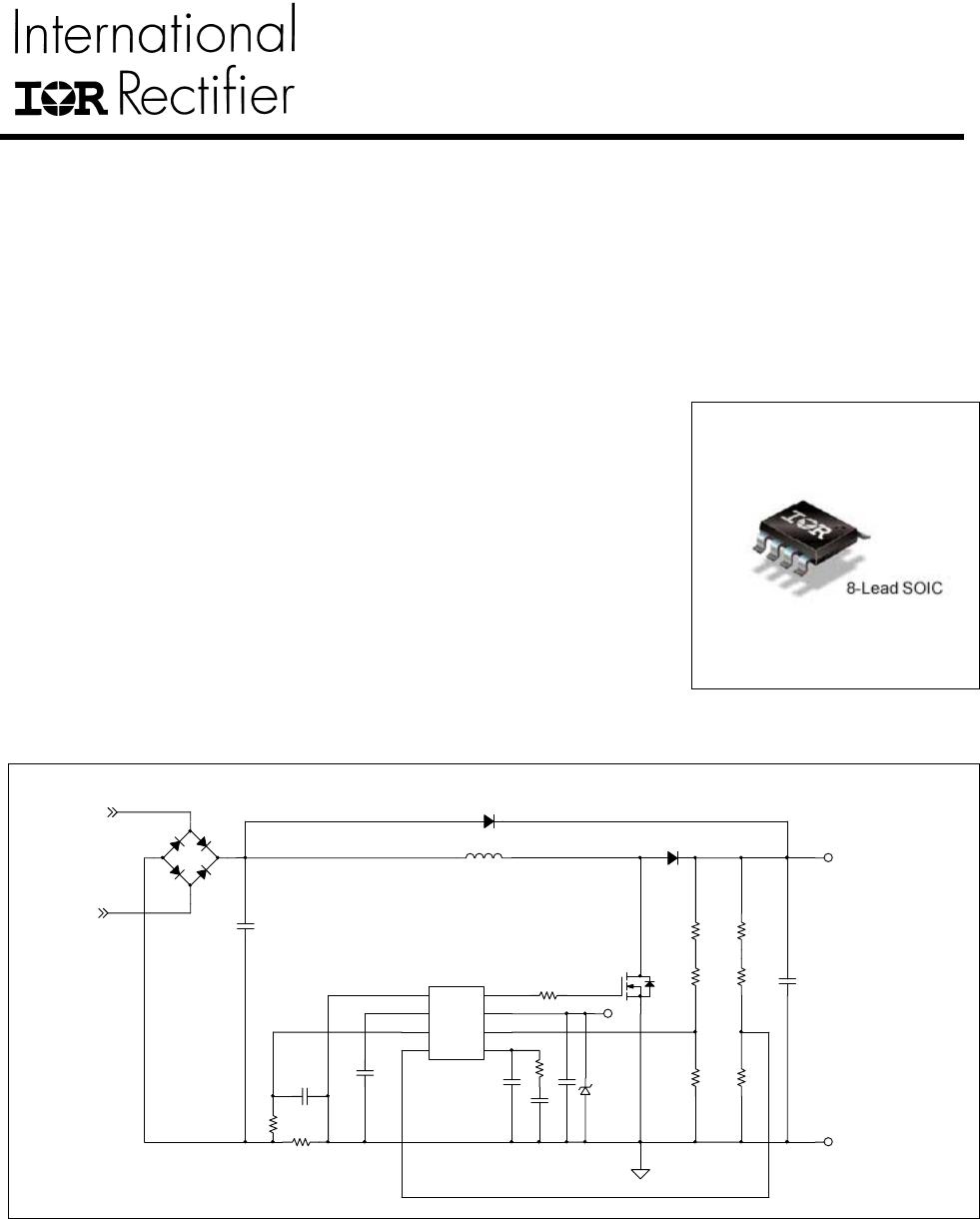
IR1155 Application Diagram
• PFC IC with IR proprietary “One Cycle Control”
• Continuous conduction mode boost type PFC
• Programmable switching frequency (48k-200kHz)
• Average current mode control
• Output overvoltage protection
• Open loop protection
• Cycle by cycle peak current limit
• VCC under voltage lockout
• Programmable soft start
• Micropower startup
• User initiated micropower “Sleep Mode
• OVP/EN pin internal filtering for higher noise immunity
• 1.5A peak gate drive
• Latch immunity and ESD protection
The μPFC IR1155 power factor correction IC, based on IR proprietary "One
Cycle Control" (OCC) technique, provides for high PF, low THD and
excellent DC Bus regulation while enabling drastic reduction in component
count, PCB area and design time as compared to traditional solutions. The
IC is designed to operate in continuous conduction mode Boost PFC
converters with average current mode control over 85-264VAC input line
voltage range. Switching frequency can be programmed to anywhere
between 48kHz to 200kHz based on the specific application requirement.
In addition, IR1155 offers several advanced system-enabling and protective
features such as dedicated pin for over voltage protection, cycle by cycle
peak current limitation, open loop protection, V
CC
UVLO, soft-start and
micropower startup/sleep-mode with IC current consumption less than
200µA. The sleep mode, invoked by pulling the OVP/EN pin low, enables
compliance with standby power requirements mandated by regulations
such as Energy Star, Green Power, Blue Angel etc.
AC LINE
VOUT
A
C NEUTRAL
VCC
RTN
-+
COM
1
OVP
4
VFB
6
VCC
7
GATE
8
ISNS
3
FREQ
2
COMP
5
IR1155S
IR1155S
www.irf.com 2
© 2011 International Rectifier
Qualification Information
Industrial
Qualification Level
Comments: This family of ICs has passed JEDEC’s Industrial
qualification. IR’s Consumer qualification level is granted by
extension of the higher Industrial level.
Moisture Sensitivity Level
MSL2 260°C
(per IPC/JEDEC J-STD-020)
Machine Model
Class A
(per JEDEC standard JESD22-A115)
ESD
Human Body Model
Class 1B (passes 500V)
(per EIA/JEDEC standard EIA/JESD22-A114)
IC Latch-Up Test
Class I, Level A
(per JESD78)
RoHS Compliant Yes
Absolute Maximum Ratings
Parameter Symbol Min. Max. Units Remarks
VCC Voltage V
CC
-0.3 20 V
FREQ Voltage V
FREQ
-0.3 6.5 V
ISNS Voltage V
ISNS
-10 0.3 V
VFB, OVP Voltage V
FB
, V
OVP
-0.3 6.5 V
COMP Voltage V
COMP
-0.3 6.5 V
GATE Voltage V
GATE
-0.3 18 V
ISNS Current I
ISNS
-2 2 mA
Junction Temperature T
J
-40 150 °C
Storage Temperature T
S
-55 150 °C
Thermal Resistance
Junction to Ambient
R
θJA
128 °C/W
Package Power Dissipation P
D
976 mW T
AMB
= 25°C
Recommended Operating Conditions
Recommended operating conditions for reliable operation with margin
Parameter Symbol Min. Typ. Max. Units Remarks
Supply Voltage V
CC
12 19 V
Junction Temperature T
J
-25 125 °C
Switching Frequency F
SW
48 200 kHz
IR1155S
www.irf.com 3
© 2011 International Rectifier
Electrical Characteristics
The electrical characteristics involve the spread of values guaranteed within the specified supply voltage and
junction temperature range T
J
from –25 °C to 125°C. Typical values represent the median values, which are
related to 25°C. If not otherwise stated, a supply voltage of V
CC
=15V is assumed for test condition.
Supply Section
Parameter Symbol Min. Typ. Max. Units Remarks
VCC Turn On
Threshold
V
CC
ON
10.65 11.3 11.95 V
VCC Turn Off
Threshold (Under
Voltage Lock Out)
V
CC UVLO
9.2 9.8 10.4 V
VCC Turn On/Off
Hysteresis
V
CC HYST
1.5 V
Operating Current I
CC
10 13 mA C
load
=1nF, F
SW
=181kHz
6 8 mA
Standby Mode (Inactive Gate,
Inactive Internal Oscillator)
V
FB
<V
OLP
See State Transition Diagram
Startup Current I
CCSTART
175 uA V
CC
=V
CC ON
- 0.1V
Sleep Current I
SLEEP
125 200 uA
Sleep Mode (Inactive Gate,
Inactive Oscillator)
- V
OVP
<V
SLEEP,OFF
See State Transition Diagram
Sleep Mode
Threshold (Enable)
V
SLEEP,ON
0.80 0.90 1.00 V
IC Enable threshold,
Bias on OVP pin
Sleep Mode
Threshold (Disable)
V
SLEEP,OFF
0.53 0.60 0.67 V
IC Disable threshold,
Bias on OVP pin

IR1155STRPBF

Mfr. #:
Manufacturer:
Infineon Technologies
Description:
Power Factor Correction - PFC Prog FREQ 1 CYCLE Cntrl PFC IC
Lifecycle:
New from this manufacturer.
Delivery:
DHL FedEx Ups TNT EMS
Payment:
T/T Paypal Visa MoneyGram Western Union

Products related to this Datasheet