LT3032 Series
13
3032ff
For more information www.linear.com/LT3032
TYPICAL PERFORMANCE CHARACTERISTICS
OUTN, 10Hz to 100kHz
Output Noise, C
BYPN
= 0
1ms/DIVC
OUTN
= 10µF
I
LOAD
= –150mA
V
OUTN
= –5V
V
OUTN
200µV/DIV
3032 G46
OUTP 10Hz to 100kHz Output Noise
C
BYPP
= 0.01µF
1ms/DIVC
OUTP
= 10µF
I
L
= 150mA
V
OUTP
= 5V
V
OUTP
100µV/DIV
3032 G45
OUTP 10Hz to 100kHz Output Noise
C
BYPP
= 0
1ms/DIVC
OUTP
= 10µF
I
L
= 150mA
V
OUTP
= 5V
V
OUTP
100µV/DIV
3032 G44
OUTN, 10Hz to 100kHz Output
Noise, C
BYPN
= 0.01µF
OUTP Transient Response
C
BYPP
= 0
V
OUTN
100µV/DIV
1ms/DIVC
OUTN
= 10µF
I
LOAD
= –150mA
V
OUTN
= –5V
3032 G47
TIME (µs)
0.3
0.2
0.1
0
–0.1
–0.2
–0.3
OUTP VOLTAGE
DEVIATION (V)
150
100
50
0
LOAD CURRENT
(mA)
3032 G48
0 400
800
1200 1600 2000
V
OUTP
= 5V
V
INP
= 6V
C
INP
= 10µF
C
OUTP
= 10µF
OUTN RMS Noise
vs Load Current (10Hz to 100kHz)
140
120
100
80
60
40
20
0
LOAD CURRENT (mA)
OUTN RMS NOISE (µV
RMS
)
–0.01
3032 G43
LT3032
LT3032-5
LT3032-3.3
LT3032-12
LT3032-15
–1 –10 –1k–0.1
LT3032
LT3032-5
LT3032-12
LT3032-15
LT3032-3.3
–100
C
BYPN
= 0
C
BYPN
= 0.01µF
C
OUTN
= 10µF
OUTN RMS Noise
vs Bypass Capacitor
C
BYPN
(pF)
10
OUTN RMS NOISE (µV
RMS
)
250
200
150
100
50
0
LT3032-5
100 1k 10k
3032 G42
C
OUTN
= 10µF
I
L
= –150mA
f = 10Hz TO 100kHz
LT3032
LT3032-15
LT3032-12
LT3032-3.3
OUTP RMS Noise
vs Load Current (10Hz to 100kHz)
LOAD CURRENT (mA)
0.01
OUTP RMS NOISE (µV
RMS
)
350
300
250
200
150
100
50
0
0.1 1
3032 G41
10 100 1k
LT3032
LT3032-5
LT3032-3.3
LT3032-12
LT3032-15
C
OUTP
= 10µF
C
BYPP
= 0
C
BYPP
= 0.01µF
LT3032-3.3
LT3032-5
LT3032
LT3032-12
LT3032-15
OUTP RMS Noise
vs Bypass Capacitor
C
BYPP
(pF)
10
OUTP RMS NOISE (µV
RMS
)
350
300
250
200
150
100
50
0
100 1k 10k
3032 G40
C
OUTP
= 10µF
I
L
= 150mA
f = 10Hz TO 100kHz
LT3032
LT3032-5
LT3032-3.3
LT3032-15
LT3032-12
LT3032 Series
14
3032ff
For more information www.linear.com/LT3032
PIN FUNCTIONS
OUTP (Pin 1): Positive Output. This output supplies power
to the positive side load. A minimum output capacitor
of 2.2µF is required to prevent oscillations. Larger out
-
put capacitors are required for applications with large
transient loads to limit peak voltage transients. See the
Applications Information section for more information
on output capacitance, bypass capacitance, and reverse
output characteristics.
ADJP (Pin 2, Adjustable Part Only): Positive Adjust. This
is the input to the positive side error amplifier. This pin
is internally clamped to ±7V. It has a typical bias current
of 30nA which flows into the pin (see curve of ADJP Pin
Bias Current vs Temperature in the Typical Performance
Characteristics). The ADJP pin voltage is 1.22V referenced
to ground and the output voltage range is 1.22V to 20V.
BYPP (Pin 3): Positive Bypass. The BYPP pin is used to
bypass the reference of the positive side regulator to achieve
low noise performance. The BYPP pin is clamped internally
to ±0.6V (one V
BE
). A small capacitor from OUTP to this pin
will bypass the reference to lower the output voltage noise.
A maximum value of 0.01µF is used for reducing output
voltage noise to a typical 20µV
RMS
over the 10Hz to 100kHz
bandwidth. If not used, this pin must be left unconnected.
GND (Pins 4, 5, Exposed Pad Pin 15): Ground. One of
the DFN’s exposed backside pads (Pin 15) is an electrical
connection to ground. To ensure proper electrical and
thermal performance, solder Pin 15 to the PCB’s ground
and tie directly to Pins 4 and 5. Connect the bottom of
the positive and negative output voltage setting resistor
dividers directly to Pins 4 and 5 for optimum load regula
-
tion performance.
INN (
Pin 6, 9, Exposed Pad Pin 16): Negative Input. The
DFN package’s second exposed backside pad (Pin 16) is
an electrical connection to INN. To ensure proper electri
-
cal and thermal performance, solder Pin 16 to the PCB’s
negative
input supply and tie directly to Pins 6 and 9.
Power is
supplied to the negative side of the LT3032
through
the INN pins. A bypass capacitor is required on
this pin if it is more than six inches away from the main
input filter capacitor. In general, the output impedance of
a battery rises with frequency, so it is advisable to include
a bypass capacitor in battery-powered circuits. A bypass
capacitor in the range of 1µF to 10µF is sufficient.
TYPICAL PERFORMANCE CHARACTERISTICS
OUTP Transient Response
C
BYPP
= 0.01µF
TIME (µs)
0.04
0.02
0
–0.02
–0.04
OUTP VOLTAGE
DEVIATION (V)
150
100
50
0
LOAD CURRENT
(mA)
3032 G49
0 40
80
120 160 200
V
OUTP
= 5V
V
INP
= 6V
C
INP
= 10µF
C
OUTP
= 10µF
OUTN Transient Response
C
BYPN
= 0
OUTN Transient Response
C
BYPN
= 0.01µF
TIME (µs)
0.2
0.1
0
–0.2
–0.1
0
–50
–150
–100
OUTN VOLTAGE
DEVIATION (V)
LOAD CURRENT
(mA)
3032 G50
0 100 200 300 400 500 600 700 800 900 1k
V
OUTN
= –5V
V
INN
= –6V
C
INN
= 10µF
C
OUTN
= 10µF
TIME (µs)
0.04
0.06
0.02
0
–0.02
–0.04
–0.06
–50
0
–100
–150
OUTN VOLTAGE
DEVIATION (V)
LOAD CURRENT
(mA)
3032 G51
0 50 100 150 200 250 300 350 400 450 500
V
OUTN
= –5V
V
INN
= –6V
C
INN
= 10µF
C
OUTN
= 10µF
LT3032 Series
15
3032ff
For more information www.linear.com/LT3032
OUTN (Pin 7): Negative Output. This output supplies power
to the negative side load. A minimum output capacitor
ofF is required to prevent oscillations. Larger output
capacitors are required for applications with large tran-
sient loads to limit peak voltage transients. A parasitic
diode exists between OUTN and INN; OUTN can not be
pulled more negative than INN during normal operation,
or more than 0.5V below INN during a fault condition. See
the Applications Information section for more information
on output capacitance and bypass capacitors.
ADJN (Pin 8, Adjustable Part Only): Negative Adjust. This
is the input to the negative side error amplifier. The ADJN
pin has a typical bias current of 30nA that flows out of the
pin. The ADJN pin voltage is –1.22V referenced to ground,
and the output voltage range is –1.22V to –20V. A parasitic
diode exists between ADJN and INN. The ADJN pin cannot
be pulled more negative than INN during normal operation,
or more than 0.5V below INN during a fault condition.
SHDNN (Pin 10): Negative Shutdown. The SHDNN pin puts
the negative side into a low power shutdown state. The
SHDNN pin is referenced to ground for regulator control,
allowing the negative side
to be driven by either positive
or negative logic. The negative output will be off if the
SHDNN pin is within ±0.8V(typical) of ground. Pulling the
SHDNN pin more than –1.9V or +1.4V(typical) will turn the
negative output on. The SHDNN pin can be driven by 5V
logic or open-collector logic with a pull-up resistor. The
pull-up resistor is required to supply the pull-up current of
the open-collector device, normally several microamperes,
and the SHDNN pin current, typicallyA out of the pin
(for negative logic) orA into the pin (for positive logic).
If unused, the SHDNN pin must be connected to INN. The
negative output will be shut down if the SHDNN pin is open
circuit. A parasitic diode exists between SHDNN and INN,
the SHDNN pin cannot be pulled more negative than INN
during normal operation, or more than 0.5V below INN
during a fault condition.
PIN FUNCTIONS
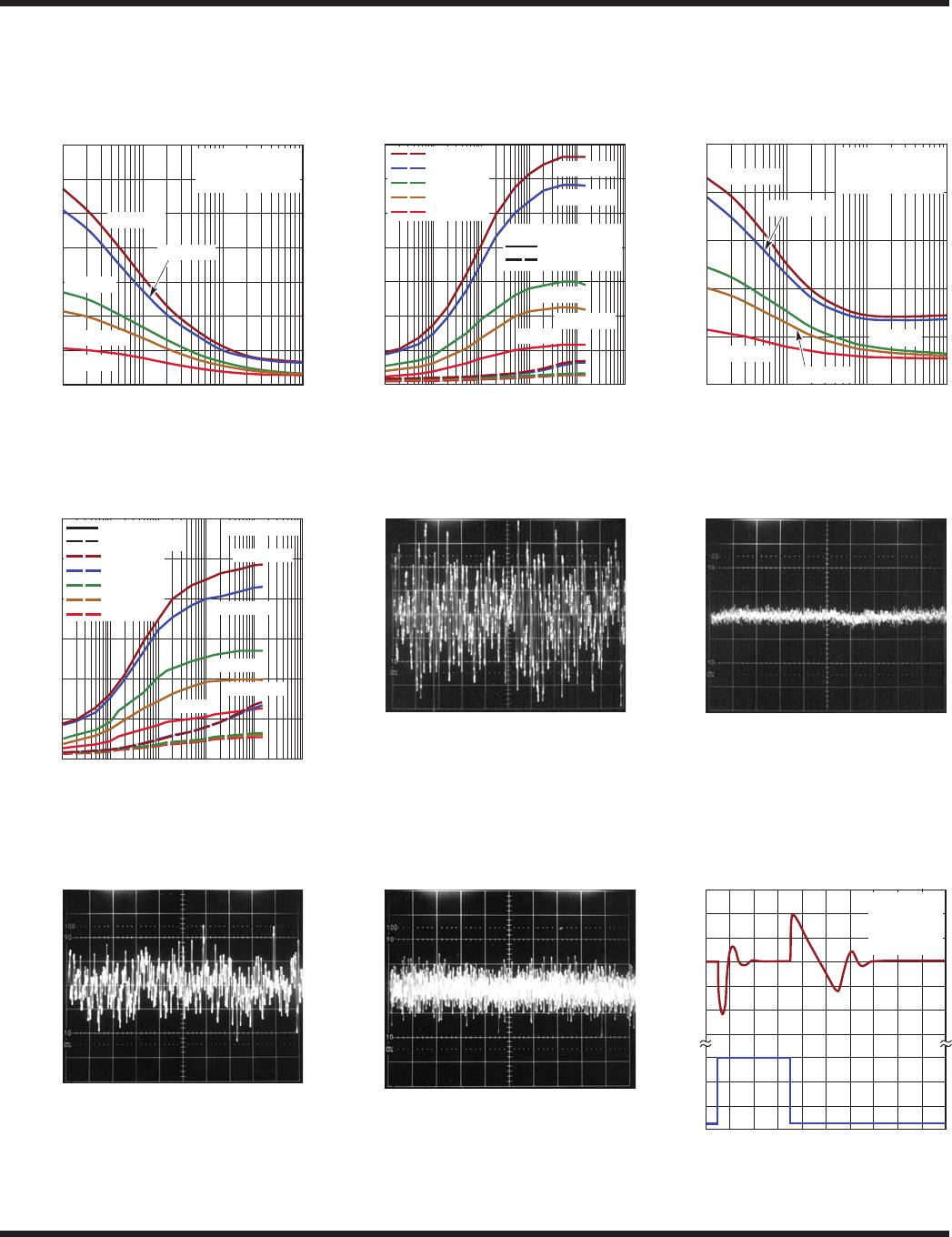
BYPN (Pin 11): Negative Bypass. The BYPN pin is used
to bypass the reference of the negative side regulator to
achieve low noise performance. A small capacitor from
OUTN to this pin will bypass the reference to lower the
output voltage noise.
A maximum value of 0.01µF is used
for
reducing output voltage noise to a typical 30µV
RMS
over the 10Hz to 100kHz bandwidth. If not used, this pin
must be left unconnected.
SHDNP (Pin 12): Positive Shutdown. The SHDNP pin puts
the positive side into a low power shutdown state. The
positive output will be off when the SHDNP pin is pulled
below 0.6V(typical). The SHDNP pin can be driven by 5V
logic or open-collector logic with a pull-up resistor. The
pull-up resistor is required to supply the pull-up current
of the open-collector device, normally several microam
-
peres, and the SHDNP
pin current, typicallyA into the
pin. If unused, the SHDNP pin must be connected to INP.
The positive output will be shut down if the SHDNP pin
is open circuit. The SHDNP pin can be tied directly to the
SHDNN pin and both pins driven directly by positive logic
for a single point control of both outputs.
NC (Pin 13/Pins 2, 8 for Fixed Voltage Devices): No
Connect. The No Connect pin has no connection to inter
-
nal cir
cuitry and may be tied to INP, GND, INN, SHDNP
,
SHDNN, OUTP, OUTN, floated, or tied to any other point.
INP (
Pin 14): Positive Input. Power is supplied to the
positive side of the LT3032 through the INP pin. A bypass
capacitor is required on this pin if it is more than six inches
away from the main input filter capacitor. In general, the
output impedance of a battery rises with frequency, so
it is advisable to include a bypass capacitor in battery-
powered circuits. A bypass capacitor in the range ofF
to 10µF is sufficient.

LT3032EDE-3.3#PBF

Mfr. #:
Manufacturer:
Analog Devices / Linear Technology
Description:
LDO Voltage Regulators Dual 200mA Positive/Negative, Low Noise, Low Dropout Linear Regulator
Lifecycle:
New from this manufacturer.
Delivery:
DHL FedEx Ups TNT EMS
Payment:
T/T Paypal Visa MoneyGram Western Union