1
FN3076.15
HFA3046, HFA3096, HFA3127, HFA3128
Ultra High Frequency Transistor Arrays
The HFA3046, HFA3096, HFA3127 and the HFA3128 are
Ultra High Frequency Transistor Arrays that are fabricated
from Intersil Corporation’s complementary bipolar UHF-1
process. Each array consists of five dielectrically isolated
transistors on a common monolithic substrate. The NPN
transistors exhibit a f
T
of 8GHz while the PNP transistors
provide a f
T
of 5.5GHz. Both types exhibit low noise (3.5dB),
making them ideal for high frequency amplifier and mixer
applications.
The HFA3046 and HFA3127 are all NPN arrays while the
HFA3128 has all PNP transistors. The HFA3096 is an
NPN-PNP combination. Access is provided to each of the
terminals for the individual transistors for maximum
application flexibility. Monolithic construction of these
transistor arrays provides close electrical and thermal
matching of the five transistors.
Intersil provides an Application Note illustrating the use of
these devices as RF amplifiers. For more information, visit
our website at www.intersil.com.
Features
NPN Transistor (f
T
) . . . . . . . . . . . . . . . . . . . . . . . . . 8GHz
NPN Current Gain (h
FE
). . . . . . . . . . . . . . . . . . . . . . . . 130
NPN Early Voltage (V
A
) . . . . . . . . . . . . . . . . . . . . . . . 50V
PNP Transistor (f
T
). . . . . . . . . . . . . . . . . . . . . . . . .5.5GHz
PNP Current Gain (h
FE
). . . . . . . . . . . . . . . . . . . . . . . . . 60
PNP Early Voltage (V
A
) . . . . . . . . . . . . . . . . . . . . . . . .20V
Noise Figure (50) at 1.0GHz . . . . . . . . . . . . . . . . . 3.5dB
Collector to Collector Leakage. . . . . . . . . . . . . . . . . .<1pA
Complete Isolation Between Transistors
Pin Compatible with Industry Standard 3XXX Series
Arrays
Pb-Free (RoHS Compliant)
Applications
VHF/UHF Amplifiers
VHF/UHF Mixers
IF Converters
Synchronous Detectors
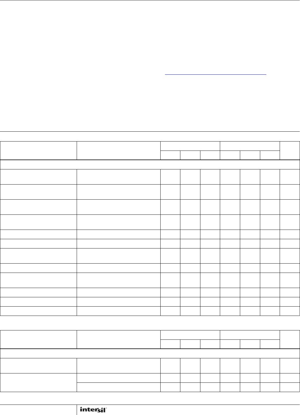
Ordering Information
PART NUMBER
(Note)
PART
MARKING
TEMP. RANGE
(°C)
PACKAGE
(Pb-free)
PKG.
DWG. #
HFA3046BZ HFA3046BZ -55 to +125 14 Ld SOIC M14.15
HFA3096BZ* HFA3096BZ -55 to +125 16 Ld SOIC M16.15
HFA3127BZ* HFA3127BZ -55 to +125 16 Ld SOIC M16.15
HFA3127RZ* 127Z -55 to +125 16 Ld 3x3 QFN L16.3x3
HFA3128BZ (No longer
available or supported)
HFA3128BZ -55 to +125 16 Ld SOIC M16.15
HFA3128RZ (No longer
available or supported)
128Z -55 to +125 16 Ld 3x3 QFN L16.3x3
*Add “96” suffix for tape and reel.
NOTE: These Intersil Pb-free plastic packaged products employ special Pb-free material sets, molding compounds/die attach materials, and 100%
matte tin plate plus anneal (e3 termination finish, which is RoHS compliant and compatible with both SnPb and Pb-free soldering operations).
Intersil Pb-free products are MSL classified at Pb-free peak reflow temperatures that meet or exceed the Pb-free requirements of IPC/JEDEC J
STD-020.
Data Sheet August 11, 2015
CAUTION: These devices are sensitive to electrostatic discharge; follow proper IC Handling Procedures.
1-888-INTERSIL or 1-888-468-3774
| Copyright Intersil Americas LLC 1998, 2005, 2013, 2015. All Rights Reserved
Intersil (and design) is a trademark owned by Intersil Corporation or one of its subsidiaries.
All other trademarks mentioned are the property of their respective owners.
2
FN3076.15
August 11, 2015
Pinouts
HFA3046
(14 LD SOIC)
TOP VIEW
HFA3096
(16 LD SOIC)
TOP VIEW
HFA3127
(16 LD SOIC)
TOP VIEW
HFA3128
(16 LD SOIC)
TOP VIEW
HFA3127, HFA3128
(16 LD 3X3 QFN)
TOP VIEW
1
2
3
4
5
6
7
14
13
12
11
10
9
8
Q
1
Q
2
Q
3
Q
4
Q
5
14
15
16
9
13
12
11
10
1
2
3
4
5
7
6
8
Q
1
NC
Q
3
Q
4
Q
2
Q
5
14
15
16
9
13
12
11
10
1
2
3
4
5
7
6
8
Q
1
Q
2
Q
3
Q
4
NC
Q
5
14
15
16
9
13
12
11
10
1
2
3
4
5
7
6
8
Q
1
Q
2
Q
3
Q
4
NC
Q
5
1
3
4
15
Q2E
Q2B
NC
Q3C
Q2C
Q1C
Q1E
Q1B
16 14 13
2
12
10
9
11
6578
Q5B
Q5E
Q5C
Q4C
Q3E
Q3B
Q4B
Q4E
HFA3046, HFA3096, HFA3127, HFA3128
3
FN3076.15
August 11, 2015
Absolute Maximum Ratings Thermal Information
Collector to Emitter Voltage (Open Base) . . . . . . . . . . . . . . . . . . 8V
Collector to Base Voltage (Open Emitter) . . . . . . . . . . . . . . . . . 12V
Emitter to Base Voltage (Reverse Bias). . . . . . . . . . . . . . . . . . . 5.5V
Collector Current (100% Duty Cycle) . . . . . 18.5mA at T
J
= +150°C
34mA at T
J
= +125°C
37mA at T
J
= +110°C
Peak Collector Current (Any Condition). . . . . . . . . . . . . . . . . . 65mA
Operating Information
Temperature Range . . . . . . . . . . . . . . . . . . . . . . . . -55°C to +125°C
Thermal Resistance (Typical)
JA
(°C/W)
JC
(°C/W)
14 Ld SOIC Package (Note 1) . . . . . . . 120 N/A
16 Ld SOIC Package (Note 1) . . . . . . . 115 N/A
QFN Package (Notes 2, 3). . . . . . . . . . 57 10
Maximum Power Dissipation (Any One Transistor) . . . . . . . . 0.15W
Maximum Junction Temperature (Die) . . . . . . . . . . . . . . . . . . +175°C
Maximum Junction Temperature (Plastic Package) . . . . . . +150°C
Maximum Storage Temperature Range . . . . . . . . . -65°C to +150°C
Pb-Free Reflow Profilesee link below
http://www.intersil.com/pbfree/Pb-FreeReflow.asp
CAUTION: Stresses above those listed in “Absolute Maximum Ratings” may cause permanent damage to the device. This is a stress only rating and operation of the
device at these or any other conditions above those indicated in the operational sections of this specification is not implied.
NOTES:
1.
JA
is measured with the component mounted on an evaluation PC board in free air.
2. For
JC
, the “case temp” location is the center of the exposed metal pad on the package underside.
3.
JA
is measured with the component mounted on a high effective thermal conductivity test board in free air. See Tech Brief TB379 for details.
Electrical Specifications T
A
= +25°C
PARAMETER TEST CONDITIONS
DIE SOIC, QFN
UNITSMIN TYP MAX MIN TYP MAX
DC NPN CHARACTERISTICS
Collector to Base Breakdown
Voltage, V
(BR)CBO
I
C
= 100µA, I
E
= 0 12 18 - 12 18 - V
Collector to Emitter Breakdown
Voltage, V
(BR)CEO
I
C
= 100µA, I
B
= 0 8 12 - 8 12 - V
Collector to Emitter Breakdown
Voltage, V
(BR)CES
I
C
= 100µA, Base Shorted to Emitter 10 20 - 10 20 - V
Emitter to Base Breakdown
Voltage, V
(BR)EBO
I
E
= 10µA, I
C
= 0 5.5 6 - 5.5 6 - V
Collector-Cutoff-Current, I
CEO
V
CE
= 6V, I
B
= 0 - 2 100 - 2 100 nA
Collector-Cutoff-Current, I
CBO
V
CB
= 8V, I
E
= 0 - 0.1 10 - 0.1 10 nA
Collector to Emitter Saturation
Voltage, V
CE(SAT)
I
C
= 10mA, I
B
= 1mA - 0.3 0.5 - 0.3 0.5 V
Base to Emitter Voltage, V
BE
I
C
= 10mA - 0.85 0.95 - 0.85 0.95 V
DC Forward-Current Transfer
Ratio, h
FE
I
C
= 10mA, V
CE
= 2V 40 130 - 40 130 -
Early Voltage, V
A
I
C
= 1mA, V
CE
= 3.5V 20 50 - 20 50 - V
Base to Emitter Voltage Drift I
C
= 10mA - -1.5 - - -1.5 - mV/°C
Collector to Collector Leakage - 1 - - 1 - pA
Electrical Specifications T
A
= +25°C
PARAMETER TEST CONDITIONS
DIE SOIC, QFN
UNITSMIN TYP MAX MIN TYP MAX
DYNAMIC NPN CHARACTERISTICS
Noise Figure f = 1.0GHz, V
CE
= 5V,
I
C
= 5mA, Z
S
= 50
- 3.5 - - 3.5 - dB
f
T
Current Gain-Bandwidth
Product
I
C
= 1mA, V
CE
= 5V - 5.5 - - 5.5 - GHz
I
C
= 10mA, V
CE
= 5V - 8 - - 8 - GHz
HFA3046, HFA3096, HFA3127, HFA3128

HFA3046BZ

Mfr. #:
Manufacturer:
Renesas / Intersil
Description:
RF Bipolar Transistors W/ANNEAL TXARRAY 3X NPN + NPN DIFF PAIR
Lifecycle:
New from this manufacturer.
Delivery:
DHL FedEx Ups TNT EMS
Payment:
T/T Paypal Visa MoneyGram Western Union