LT3080
16
3080fc
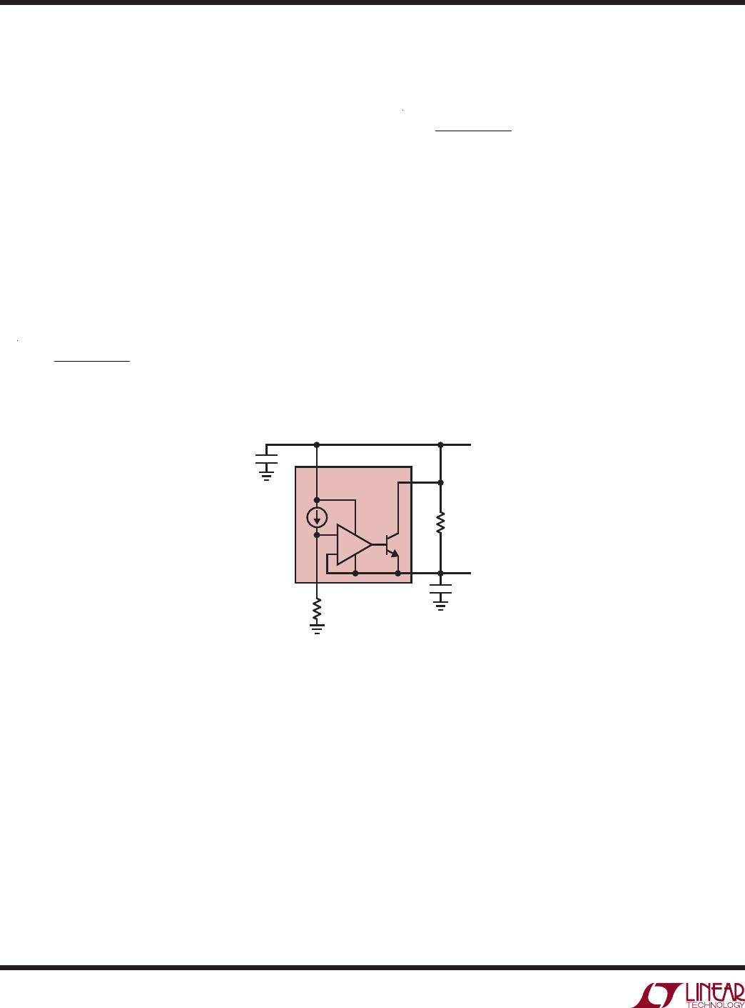
The second technique for reducing power dissipation,
shown in Figure 9, uses a resistor in parallel with the
LT3080. This resistor provides a parallel path for current
flow, reducing the current flowing through the LT3080.
This technique works well if input voltage is reasonably
constant and output load current changes are small. This
technique also increases the maximum available output
current at the expense of minimum load requirements.
As an example, assume: V
IN
= V
CONTROL
= 5V, V
IN(MAX)
=
5.5V, V
OUT
= 3.3V, V
OUT(MIN)
= 3.2V, I
OUT(MAX)
= 1A and
I
OUT(MIN)
= 0.7A. Also, assuming that R
P
carries no more
than 90% of I
OUT(MIN)
= 630mA.
Calculating R
P
yields:
R
P
=
0.63A
= 3.65Ω
(5% Standard value = 3.6Ω)
The maximum total power dissipation is (5.5V – 3.2V) •
1A = 2.3W. However the LT3080 supplies only:
1A –
3.6Ω
= 0.36A
Therefore, the LT3080’s power dissipation is only:
P
DIS
= (5.5V – 3.2V) • 0.36A = 0.83W
R
P
dissipates 1.47W of power. As with the first technique,
choose appropriate wattage resistors to handle and dis-
sipate the power properly. With this configuration, the
LT3080 supplies only 0.36A. Therefore, load current can
increase by 0.64A to 1.64A while keeping the LT3080 in
its normal operating range.
Figure 9. Reducing Power Dissipation Using a Parallel Resistor
+
–
LT3080
IN
V
CONTROL
OUT
V
OUT
V
IN
C2
3080 F09
SET
R
SET
R
P
C1
applicaTions inForMaTion

