MMU 0102, MMA 0204, MMB 0207 - Professional
www.vishay.com
Vishay Beyschlag
Revision: 29-Mar-16
9
Document Number: 28713
For technical questions, contact: melf@vishay.com
THIS DOCUMENT IS SUBJECT TO CHANGE WITHOUT NOTICE. THE PRODUCTS DESCRIBED HEREIN AND THIS DOCUMENT
ARE SUBJECT TO SPECIFIC DISCLAIMERS, SET FORTH AT www.vishay.com/doc?91000
TESTS AND REQUIREMENTS
All tests are carried out in accordance with the following
specifications:
EN 60115-1, generic specification
EN 60115-8 (successor of EN 140400), sectional
specification
EN 140401-803, detail specification
IEC 60068-2-xx, test methods
The components are approved under the IECQ-CECC
quality assessment system for electronic components
according to table “Temperature Coefficient and Resistance
Range”.
The parameters stated in the Test Procedures and
Requirements table are based on the required tests and
permitted limits of EN 140401-803. The table presents only
the most important tests, for the full test schedule refer to
the documents listed above. However, some additional
tests and a number of improvements against those
minimum requirements have been included.
The testing also covers most of the requirements specified
by EIA/ECA-703 and JIS-C-5201-1.
The tests are carried out under standard atmospheric
conditions in accordance with IEC 60068-1, 4.3, whereupon
the following values are applied:
Temperature: 15 °C to 35 °C
Relative humidity: 25 % to 75 %
Air pressure: 86 kPa to 106 kPa (860 mbar to 1060 mbar)
A climatic category LCT / UCT / 56 is applied, defined by the
lower category temperature (LCT), the upper category
temperature (UCT), and the duration of exposure in the
damp heat, steady state test (56 days).
The components are mounted for testing on printed circuit
boards in accordance with EN 60115-8, 2.4.2, unless
otherwise specified.
TEST PROCEDURES AND REQUIREMENTS
EN
60 115-1
CLAUSE
IEC
60 068-2
(1)
TEST
METHOD
TEST PROCEDURE
REQUIREMENTS
PERMISSIBLE CHANGE (R)
Stability for product types:
STABILITY
CLASS 0.25
OR BETTER
STABILITY
CLASS 0.5
OR BETTER
STABILITY
CLASS 1
OR BETTER
STABILITY
CLASS 2
OR BETTER
MMU 0102 10 to 221 k 1 to < 10 < 1 > 221 k
MMA 0204 10 to 332 k 1 to < 10 < 1 > 332 k
MMB 0207 10 to 1 M 1 to < 10 < 1 > 1 M
4.5 - Resistance -
± 1 % R;
±0.5 % R
± 2 % R;
±1 % R
± 5 % R;
± 2 % R;
±1 % R
± 1 % R
4.8 -
Temperature
coefficient
At (20/-55/20) °C and
(20/125/20) °C
± 100 ppm/K, ± 50 ppm/K, ± 25 ppm/K
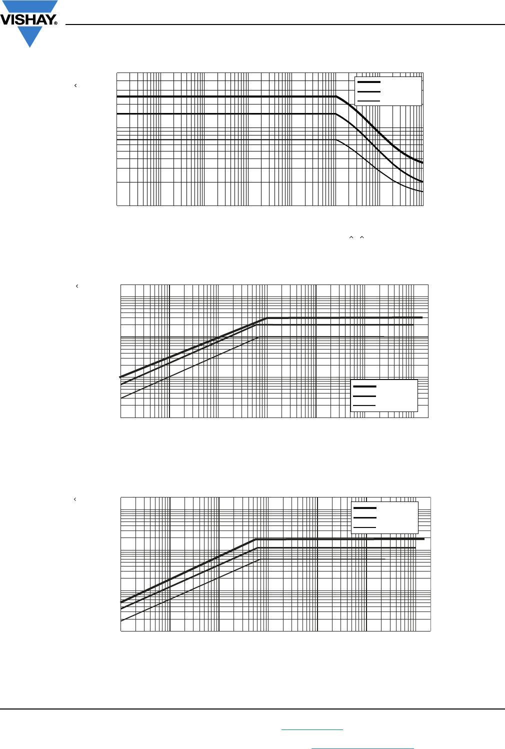
4.25.1 -
Endurance
at 70 °C:
Standard
operation
mode
U = or U = U
max.
;
whichever is the less severe;
1.5 h on; 0.5 h off;
70 °C; 1000 h ± (0.15 % R + 10 m)
± (0.5 % R
+ 10 m)
70 °C; 8000 h ± (0.3 % R + 10 m)
± (1 % R
+ 10 m)
Endurance
at 70 °C:
Power
operation
mode
U = or U = U
max.
;
whichever is the less severe;
1.5 h on; 0.5 h off;
70 °C; 1000 h ± (0.25 % R + 10 m)
± (1 % R
+ 10 m)
70 °C; 8000 h ± (0.5 % R + 10 m)
± (2 % R
+ 10 m)
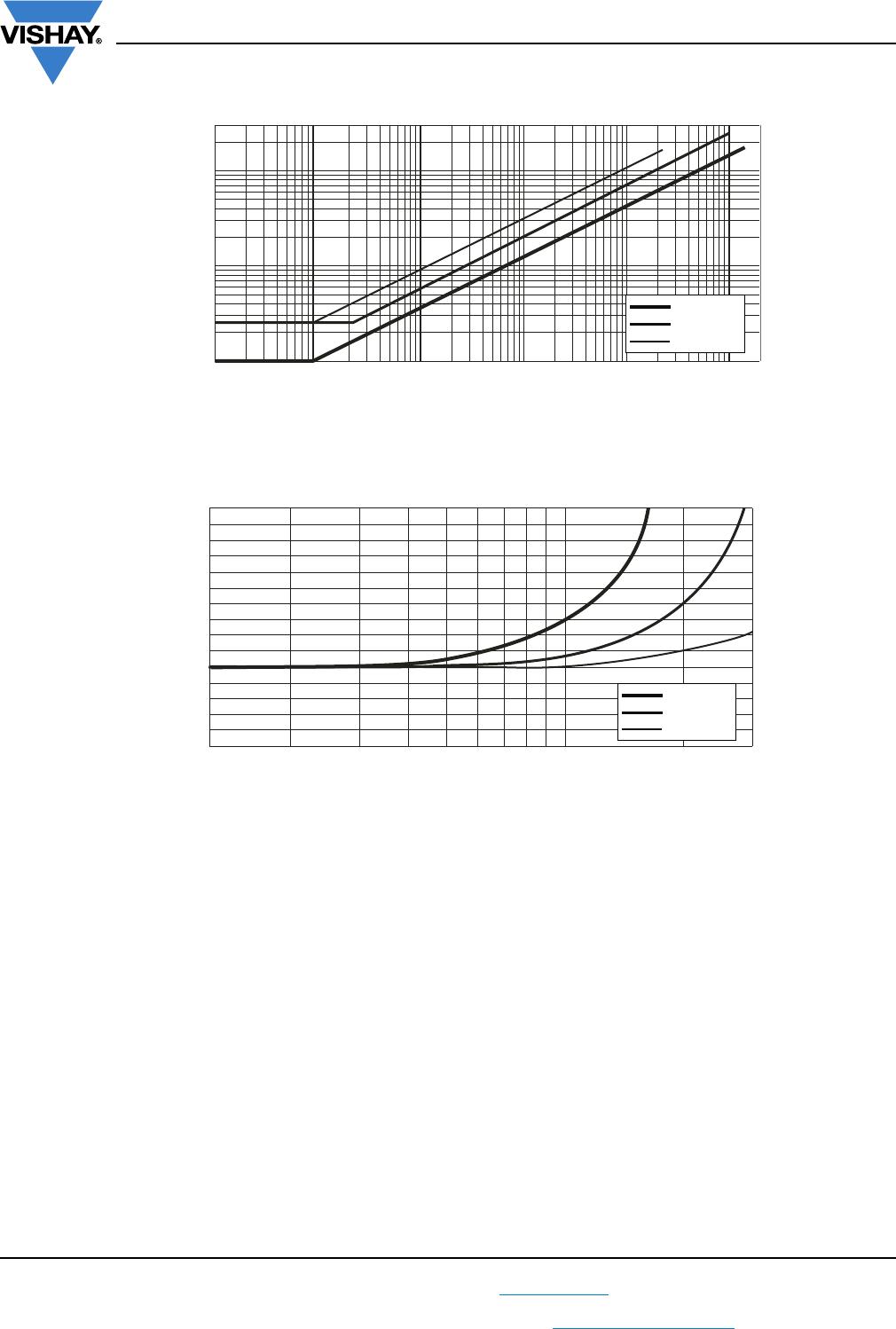
4.25.3
Endurance at
upper category
temperature
125 °C; 1000 h
±(0.15 % R
+ 5 m)
±(0.25 % R
+ 5 m)
±(0.5 % R
+ 5 m)
±(1 % R
+ 5 m)
155 °C; 1000 h
±(0.3 % R
+ 5 m)
±(0.5 % R
+ 5 m)
±(1 % R
+ 10 m)
±(2 % R
+ 5 m)
4.24 78 (Cab)
Damp heat,
steady state
(40 ± 2) °C; 56 days;
(93 ± 3) % RH
±(0.15 % R
+ 10 m)
±
(0.5 % R
+ 10 m)
±(1 % R
+ 10 m)
±(1 % R
+ 10 m)
4.37 67 (Cy)
Damp heat,
steady state,
accelerated
(85 ± 2)C;
(85 ± 5) % RH;
U = 0.3 x
100 V and
U = 0.3 x U
max.
;
(the smaller value is valid)
1000 h
±(0.25 % R
+ 10 m)
±(0.5 % R
+ 10 m)
±(1 % R
+ 10 m)
±(2 % R
+ 10 m)