2.3.2 AC Parameters: I
2
C Interface
Figure 2-3. I
2
C Synchronous Data Timing
SCL
SDA IN
SDA OUT
t
F
t
HIGH
t
LOW
t
LOW
t
R
t
AA
t
DH
t
BUF
t
SU.STO
t
SU.DAT
t
HD.DAT
t
HD.STA
t
SU.STA
Table 2-4. AC Characteristics of I2C Interface
Unless otherwise specified, applicable over recommended operating range from T
A
= -40°C to + 85°C, V
CC
= +2.0V
to +5.5V,
C
L
= 1 TTL Gate and 100 pF .
Parameter
Symbol Min. Max. Units
SCK Clock Frequency f
SCK
0 1 MHz
SCK High Time t
HIGH
400 ns
SCK Low Time t
LOW
400 ns
Start Setup Time t
SU.STA
250 ns
Start Hold Time t
HD.STA
250 ns
Stop Setup Time t
SU.STO
250 ns
Data In Setup Time t
SU.DAT
100 ns
Data In Hold Time t
HD.DAT
0 ns
Input Rise Time
(1)
t
R
300 ns
Input Fall Time
(1)
t
F
100 ns
Clock Low to Data Out Valid t
AA
50 550 ns
Data Out Hold Time t
DH
50 ns
SMBus Timeout Delay t
TIMEOUT
25 75 ms
Time bus must be free before a new transmission can start
(1)
t
BUF
500 ns
Note: 
1. Values are based on characterization and are not tested.
2. AC measurement conditions:
R
L
(connects between SDA and V
CC
): 1.2 kΩ (for V
CC
= +2.0V to +5.0V)
Input pulse voltages: 0.3V
CC
to 0.7V
CC
Input rise and fall times: ≤ 50 ns
Input and output timing reference voltage: 0.5V
CC
ATECC608A
Electrical Characteristics
© 2017 Microchip Technology Inc.
Datasheet Summary
DS40001977A-page 10
2.4 DC Parameters: All I/O Interfaces
Table 2-5. DC Parameters on All I/O Interfaces
Parameter Symbol Min. Typ. Max. Unit Conditions
Ambient Operating
Temperature
T
A
-40 +85 °C
Power Supply
Voltage
V
CC
2.0 5.5 V
Active Power
Supply Current
I
CC
2 3 mA Waiting for I/O during I/O transfers or execution of non-
ECC commands. Independent of Clock Divider value.
14 mA During ECC command execution. Clock divider = 0x0
6 mA During ECC command execution. Clock divider = 0x5
3 mA During ECC command execution. Clock divider = 0xD
Idle Power Supply
Current
I
IDLE
800 µA When device is in idle mode,
V
SDA
and V
SCL
< 0.4V or > V
CC
– 0.4
Sleep Current I
SLEEP
30 150 nA When device is in sleep mode, V
CC
≤ 3.6V,
V
SDA
and V
SCL
< 0.4V or > V
CC
– 0.4, T
A
≤ 55°C
2 µA When device is in sleep mode.
Output Low
Voltage
V
OL
0.4 V When device is in active mode,
V
CC
= 2.5 to 5.5V
Output Low
Current
I
OL
4 mA When device is in active mode,
V
CC
= 2.5 to 5.5V, V
OL
= 0.4V
Theta JA Ɵ
JA
166 °C/W SOIC (SSH)
173 °C/W UDFN (MAH)
146 °C/W RBH
2.4.1 V
IH
and V
IL
Specifications
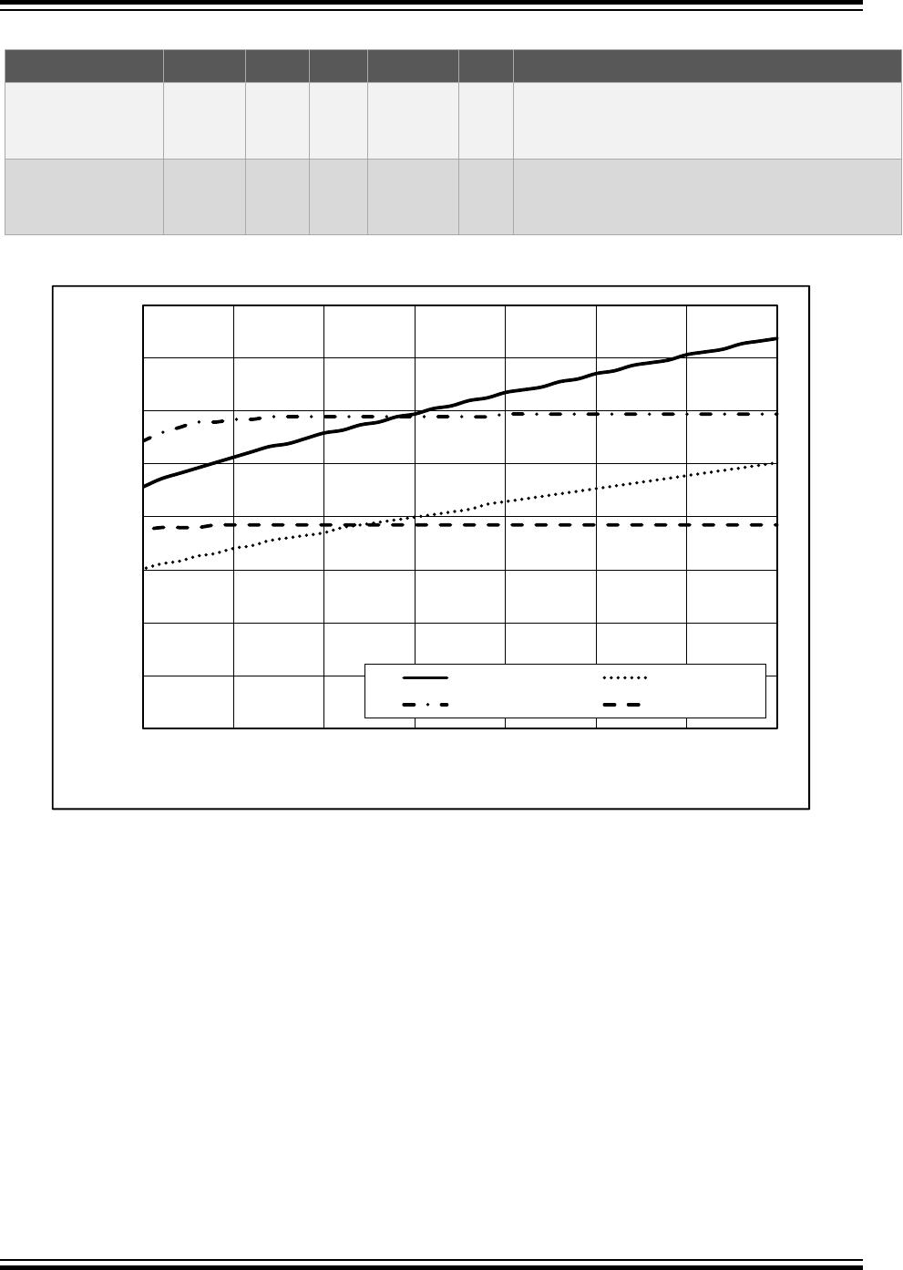
The input levels of the device will vary dependent on the mode and voltage of the device. The input
voltage thresholds when in Sleep or Idle mode are dependent on the V
CC
level as shown in Figure 2-4.
When in sleep or idle mode the TTLenable bit has no effect.
When the device is active (i.e., not in Sleep or Idle mode), the input voltage thresholds are different
depending upon the state of TTLenable (bit 1) within the ChipMode byte in the Configuration zone of the
EEPROM. If the voltage supplied to the V
CC
pin of the ATECC608A is different than the system voltage to
which the input pull-up resistor is connected, then the system designer may choose to set TTLenable to
zero, which enables a fixed input threshold by curves in VIL_ACT and VIH_ACT in Figure 2-4. Table 2-6,
which applies only when the device is active, presents the guaranteed levels of operation when operating
in this mode:
ATECC608A
Electrical Characteristics
© 2017 Microchip Technology Inc.
Datasheet Summary
DS40001977A-page 11
Table 2-6. V
IL
, V
IH
on All I/O Interfaces (TTLenable = 0)
Parameter Symbol Min. Typ. Max. Unit Conditions
Input Low Voltage V
IL
-0.5 0.5 V When device is active and TTLenable bit in
configuration memory is zero; otherwise, see
above.
Input High Voltage V
IH
1.5 V
CC
+ 0.5 V When device is active and TTLenable bit in
configuration memory is zero; otherwise, see
above.
Figure 2-4. V
IH
and V
IL
in Sleep and Idle Mode or When TTLenable = 0 on All I/O Interfaces
0
0.2
0.4
0.6
0.8
1
1.2
1.4
1.6
2 2.5 3 3.5 4 4.5 5 5.5
V
IN
(V)
V
CC
(V)
VIH_sleep VIL_sleep
VIH_Act VIL_Act
When a common voltage is used for the ATECC608A V
CC
pin and the input pull-up resistor, then the
TTLenable bit should be set to a one, which permits the input thresholds to track the supply as shown in
Figure 2-5.
ATECC608A
Electrical Characteristics
© 2017 Microchip Technology Inc.
Datasheet Summary
DS40001977A-page 12

ATECC608A-MAHDA-S

Mfr. #:
Manufacturer:
Microchip Technology
Description:
Security ICs / Authentication ICs ECC/ECDSA/ECDHE I2C small 3K reel UDFN
Lifecycle:
New from this manufacturer.
Delivery:
DHL FedEx Ups TNT EMS
Payment:
T/T Paypal Visa MoneyGram Western Union