MAX1649/MAX1651
5V/3.3V or Adjustable, High-Efficiency,
Low-Dropout, Step-Down DC-DC Controllers
_______________________________________________________________________________________ 7
Shutdown Mode
When SHDN is high, the MAX1649/MAX1651 enter shut-
down mode. In this mode, the internal biasing circuitry is
turned off (including the reference) and the supply cur-
rent drops to less than 5µA. EXT goes high, turning off the
external MOSFET. SHDN is a logic-level input. Connect
SHDN to GND for normal operation.
Quiescent Current
In normal operation, the device's typical quiescent cur-
rent is 78µA. In an actual application, even with no load,
additional current is drawn to supply external feedback
resistors (if used) and the diode and capacitor leakage
currents. In the circuit of Figure 1, with V+ at 5V and
V
OUT
at 3.3V, typical no-load supply current for the
entire circuit is 90µA.
MAX1649
MAX1651
Q
MINIMUM
OFF-TIME
ONE-SHOT
TRIG
Q
MAXIMUM
ON-TIME
ONE-SHOT
TRIG
DUAL-MODE™
COMPARATOR
ERROR
COMPARATOR
CURRENT
COMPARATOR
110mV
QS
R
FROM V+
FROM V+
CS
EXT
OUT
GND
REF
SHDN
FBV+
1.5V
REFERENCE
F/F
N
50mV
Figure 2. Block Diagram
Dual Mode is a trademark of Maxim Integrated Products, Inc.
MAX1649/MAX1651
5V/3.3V or Adjustable, High-Efficiency,
Low-Dropout, Step-Down DC-DC Controllers
8 _______________________________________________________________________________________
Modes of Operation
When delivering high output currents, the MAX1649/
MAX1651 operate in continuous-conduction mode. In
this mode, current always flows in the inductor, and
the control circuit adjusts the switch duty cycle to main-
tain regulation without exceeding the switch current
capability (Figure 3). This provides excellent load-tran-
sient response and high efficiency.
In discontinuous-conduction mode, current through the
inductor starts at zero, rises to a peak value, then
ramps down to zero. Although efficiency is still excel-
lent, the output ripple increases slightly, and the switch
waveform exhibits ringing (at the inductor's self-reso-
nant frequency). This ringing is to be expected and
poses no operational problems.
Dropout
The MAX1649/MAX1651 are in dropout when the input
voltage (V+) is low enough that the output drops below
the minimum output voltage specification (see
Electrical Characteristics). The dropout voltage is the
difference between the input and output voltage when
dropout occurs. See the Typical Operating
Characteristics for the Dropout Voltage vs. Load
Current and Dropout Voltage vs. Temperature graphs.
__________________Design Procedure
Setting the Output Voltage
The MAX1649/MAX1651 are preset for 5V and 3.3V out-
put voltages, respectively; tie FB to GND for fixed-output
operation. They may also be adjusted from 1.5V (the
reference voltage) to the input voltage, using external
resistors R2 and R3 configured as shown in Figure 4. For
adjustable-output operation, 150kΩ is recommended for
resistor R3—high enough to avoid wasting energy, yet
low enough to avoid RC delays caused by parasitic
capacitance at FB. R2 is given by:
V
OUT
R2 = R3 x
(
——— -1
)
V
REF
where V
REF
= 1.5V.
When using external resistors, it does no harm to con-
nect OUT and the output together, or to leave OUT
unconnected.
Current-Sense Resistor Selection
The current-sense resistor limits the peak switch cur-
rent to 110mV/R
SENSE
, where R
SENSE
is the value of
the current-sense resistor, and 110mV is the current-
limit trip level (see Electrical Characteristics).
V+ = 10V, I
LOAD
= 1.3A
CIRCUIT OF FIGURE 1, R1 = 75mΩ
1.5A
0A
1A
2μs/div
Figure 3. MAX1649 Continuous-Conduction Mode, Heavy
Load-Current Waveform (500mA/div)
(
)
MAX1649
MAX1651
V+
CS
GND
5
6
2
8
3
V
IN
C2
330μF
7
1
EXT
OUT
SHDN
4
C3
0.1μF
C4
0.1μF
C1
100μF
R1
0.05Ω
D1
1N5820
L1
47μH
P1
Si9430
OUTPUT
@ 1.5A
REF
FB
R2
R3
150k
R2 = R3
V
OUT
V
REF
– 1
V
REF
= 1.5V
Figure 4. Adjustable-Output Operation
MAX1649/MAX1651
5V/3.3V or Adjustable, High-Efficiency,
Low-Dropout, Step-Down DC-DC Controllers
_______________________________________________________________________________________ 9
To maximize efficiency and reduce the size and cost
of external components, minimize the peak current.
However, since the available output current is a func-
tion of the peak current, the peak current must not be
too low.
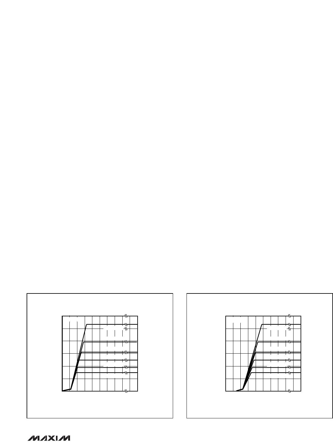
To choose the proper current-sense resistor for a par-
ticular output voltage, determine the minimum input
voltage and the maximum load current. Next, refer-
ring to Figures 5a or 5b, using the minimum input volt-
age, find the curve with the largest sense resistor that
provides sufficient output current. It is not necessary
to perform worst-case calculations. These curves take
into account the sense-resistor (±5%) and inductor
(47µH ±10%) values, the diode drop (0.4), and the
IC’s current-sense trip level (85mV); an external MOS-
FET on-resistance of 0.07Ω is assumed for V
GS
= -5V.
Standard wire-wound and metal-film resistors have an
inductance high enough to degrade performance.
Surface-mount (chip) resistors have very little inductance
and are well suited for use as current-sense resistors.
A U-shaped wire resistor made by IRC works well in
through-hole applications. Because this resistor is a
band of metal shaped as a “U”, its inductance is less
than 10nH (an order of magnitude less than metal film
resistors). Resistance values between 5mΩ and 0.1Ω
are available (see Table 1).
Inductor Selection
The MAX1649/MAX1651 operate with a wide range of
inductor values, although for most applications coils
between 10µH and 68µH take best advantage of the con-
trollers’ high switching frequency. With a high inductor
value, the MAX1649/MAX1651 will begin continuous-cur-
rent operation (see Detailed Description) at a lower frac-
tion of full-load current. In general, smaller values pro-
duce higher ripple (see below) while larger values require
larger size for a given current rating.
In both the continuous and discontinuous modes, the
lower limit of the inductor is important. With a too-small
inductor value, the current rises faster and overshoots the
desired peak current limit because the current-limit com-
parator has a finite response time (300ns). This reduces
efficiency and, more importantly, could cause the current
rating of the external components to be exceeded.
Calculate the minimum inductor value as follows:
(V+(max) - V
OUT
) x 0.3µs
L(min) = ——————————––——
ΔI x I
LIM
where ΔI is the inductor-current overshoot factor,
I
LIM
= V
CS
/R
SENSE
, and 0.3µs is the time it takes the com-
parator to switch. Set ΔI = 0.1 for an overshoot of 10%.
For highest efficiency, use a coil with low DC resis-
tance; a value smaller than 0.1V/I
LIM
works best. To
minimize radiated noise, use a toroid, pot core, or
shielded-bobbin inductor. Inductors with a ferrite core
or equivalent are recommended. Make sure the induc-
tor’s saturation-current rating is greater than I
LIM
(max).
However, it is generally acceptable to bias the inductor
into saturation by about 20% (the point where the
inductance is 20% below its nominal value).
5.0 5.4 5.8 6.2 6.6 16.0
1649 Fig05a
INPUT VOLTAGE (V)
MAXIMUM OUTPUT CURRENT (A)
3.0
2.5
2.0
1.5
1.0
0
0.5
r
s
= 0.030
V
OUT
= 5V
r
s
= 0.040
r
s
= 0.050
r
s
= 0.060
r
s
= 0.080
r
s
= 0.100
Figure 5a. MAX1649 Current-Sense Resistor Graph
3.0 3.4 3.8 4.2 4.6 16.0
1651 Fig05b
INPUT VOLTAGE (V)
MAXIMUM OUTPUT CURRENT (A)
3.0
2.5
2.0
1.5
1.0
0
0.5
r
s
= 0.030
r
s
= 0.040
r
s
= 0.050
r
s
= 0.060
r
s
= 0.080
r
s
= 0.100
V
OUT
= 3.3V
Figure 5b. MAX1651 Current-Sense Resistor Graph

MAX1649EPA

Mfr. #:
Manufacturer:
Maxim Integrated
Description:
LDO Voltage Controllers 5V/3.3V or Adjustable, High-Efficiency, Low-Dropout, Step-Down DC-DC Controller
Lifecycle:
New from this manufacturer.
Delivery:
DHL FedEx Ups TNT EMS
Payment:
T/T Paypal Visa MoneyGram Western Union