Expand menu
Hello, Sign in
My Account
0
Cart
Home
Products
Sensors
Semiconductors
Passive Components
Connectors
Power
Electromechanical
Optoelectronics
Circuit Protection
Integrated Circuits - ICs
Main Products
Manufacturers
Blog
Services
About OMO
About Us
Contact Us
Check Stock
BTS410E2NKSA1
P1-P3
P4-P6
P7-P9
P10-P12
P13-P15
BTS410E2
Data Sheet
7
2013
-
10
-
15
Short circuit detection
Fault Condition
:
V
ON
> 8.5 V typ.; IN hi
gh
Short c
irc
uit
dete
ction
L
o
g
i
c
u
n
i
t
+ V
bb
OUT
V
ON
Inductive and overv
oltage output clamp
+ V
bb
OUT
GND
P
R
O
F
E
T
V
Z
V
ON
V
ON
clamped to 68 V typ.
Overvolt. and re
verse batt. protection
+ V
bb
IN
ST
ST
R
IN
R
GND
GND
R
Sig
n
al G
ND
Logic
P
R
O
F
E
T
V
Z2
V
Z1
V
Z1
= 6.2 V typ.,
V
Z2
= 70 V typ.,
R
GND
= 150
, R
IN
,
R
ST
=
15
k
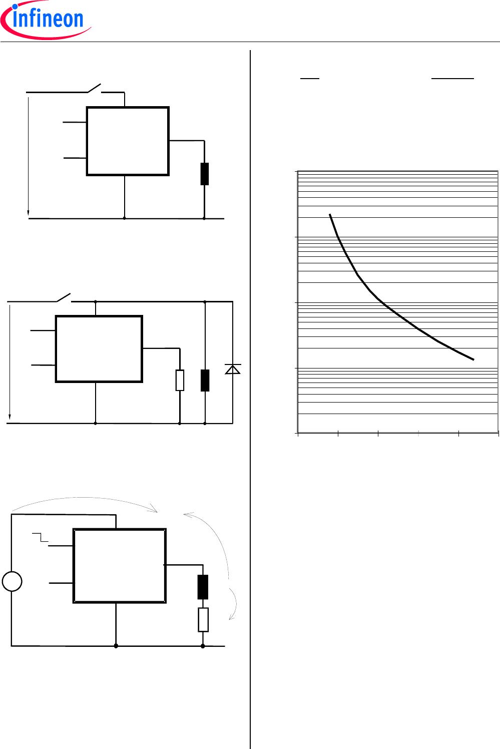
Open-load detection
ON
-state diagnostic condition
:
V
ON
<
R
ON
*
I
L(OL)
; IN
high
Ope
n l
oad
de
t
e
c
tion
L
o
g
i
c
u
n
i
t
+ V
bb
OUT
ON
V
ON
GND disconnect
PR
OF
E
T
V
IN
ST
OUT
GND
bb
V
bb
1
2
4
3
5
V
IN
V
ST
V
GND
Any kind of load. In c
ase of Input=high is
V
OUT
V
IN
-
V
IN(T+)
.
Due to V
GND
>0, no V
ST
= low signal available.
GND disconnect with GND pull
up
PR
OF
E
T
V
IN
ST
OUT
GND
bb
V
bb
1
2
4
3
5
V
GND
V
IN
V
ST
Any kind of load. If
V
GND
>
V
IN
-
V
IN(T+)
device stays
off
Due to V
GND
>0, no V
ST
= low signal available.
BTS410E2
Data Sheet
8
2013
-
10
-
15
V
bb
disconnect with energize
d inductive
load
PR
OF
E
T
V
IN
ST
OUT
GND
bb
V
bb
1
2
4
3
5
high
Normal load current can be handl
ed by the PROFET
itself.
V
bb
disconnect with charged
external
inductive load
PR
OF
E
T
V
IN
ST
OUT
GND
bb
1
2
4
3
5
V
bb
hi
gh
S
D
If other external inductive loads L are connected to the PROFET,
additional elements like D are necessary.
Inductive Load switch
-off energy
dissipation
PR
OF
E
T
V
IN
ST
OUT
GND
bb
=
E
E
E
E
AS
bb
L
R
E
Load
L
R
L
{
Z
L
Energy stored in load i
nductance:
E
L
=
1
/
2
·
L
·
I
2
L
While demag
netizing load i
nductance, the energy
dissipated in PROFET is
E
AS
= E
bb
+ E
L
- E
R
=
V
ON(CL)
·
i
L
(t) dt,
with an approximate soluti
on for R
L
0
:
E
AS
=
I
L
·
L
2
·
R
L
·
(
V
bb
+
|V
OUT(CL)
|)
·
ln
(1+
I
L
·
R
L
|V
OUT(
CL
)
|
)
Maximum allowable
load inductance fo
r
a single swi
tch off
L = f (I
L
);
T
j,start
=
150°C,
T
C
=
150°C const.,
V
bb
=
12
V,
R
L
=
0
L
[mH]
1
10
100
1000
10000
1
2
3
4
5
6
I
L
[A]
BTS410E2
Data Sheet
9
2013
-
10
-
15
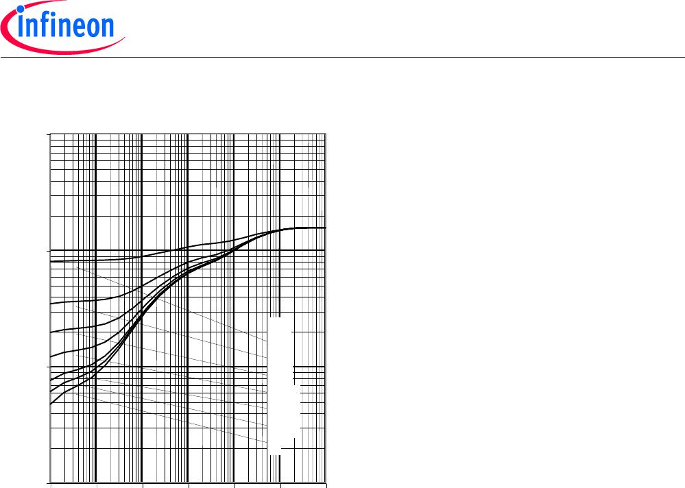
Typ. transient thermal impedance chip case
Z
thJC
=
f
(t
p
, D), D=t
p
/T
Z
thJC
[K/W]
0.01
0.1
1
10
1E-5
1E-4
1E-3
1E-2
1E
-
1
1E0
1E1
0
0.01
0.02
0.05
0.1
0.2
0.5
D=
t
p
[s]
P1-P3
P4-P6
P7-P9
P10-P12
P13-P15
BTS410E2NKSA1
Mfr. #:
Buy BTS410E2NKSA1
Manufacturer:
Infineon Technologies
Description:
IC SWITCH PWR 65V TO-220AB-5
Lifecycle:
New from this manufacturer.
Delivery:
DHL
FedEx
Ups
TNT
EMS
Payment:
T/T
Paypal
Visa
MoneyGram
Western
Union
Products related to this Datasheet
BTS410E2E3062ABUMA1
BTS410E2 E3062A
BTS410E2E3043NKSA1
BTS410E2NKSA1