MAX2039
Detailed Description
The MAX2039 can operate either as a downconverter
or an upconverter mixer that provides 7.1dB of conver-
sion loss with a typical 7.3dB noise figure. IIP3 is
+33.5dBm for upconversion and +34.5dBm for down-
conversion. The integrated baluns and matching cir-
cuitry allow for 50Ω single-ended interfaces to the RF
port and two LO ports. The RF port can be used as an
input for downconversion or an output for upconver-
sion. A single-pole, double-throw (SPDT) switch pro-
vides 50ns switching time between the two LO inputs
with 45dB of LO-to-LO isolation. Furthermore, the inte-
grated LO buffer provides a high drive level to the
mixer core, reducing the LO drive required at the
MAX2039’s inputs to a range of -3dBm to +3dBm. The
IF port incorporates a differential output for downcon-
version, which is ideal for providing enhanced IIP2 per-
formance. For upconversion, the IF port is a differential
input.
Specifications are guaranteed over broad frequency
ranges to allow for use in UMTS, cdma2000, and
2G/2.5G/3G DCS1800, and PCS1900 base stations.
The MAX2039 is specified to operate over an RF fre-
quency range of 1700MHz to 2200MHz, an LO frequen-
cy range of 1500MHz to 2000MHz, and an IF frequency
range of DC to 350MHz. Operation beyond these
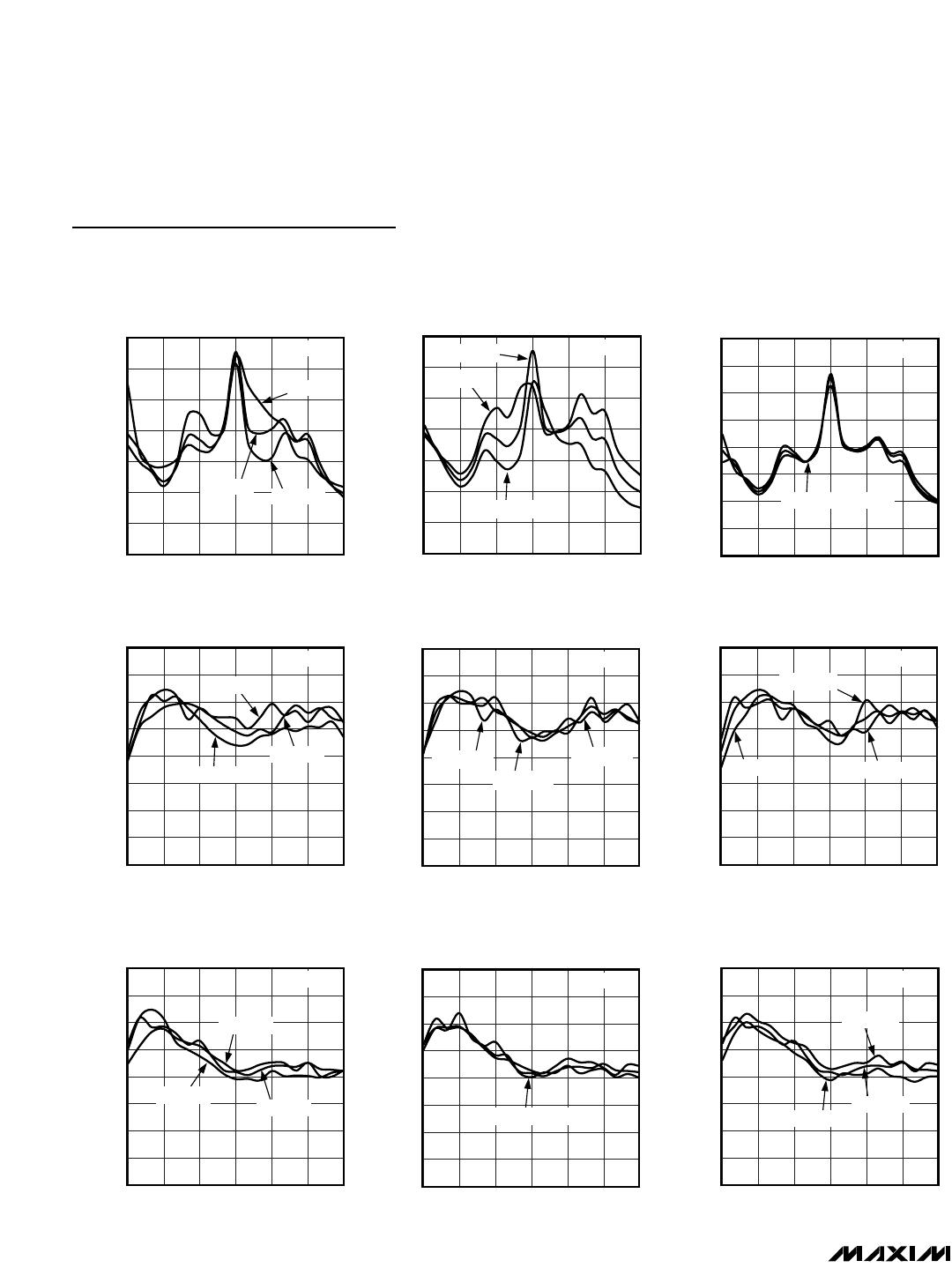
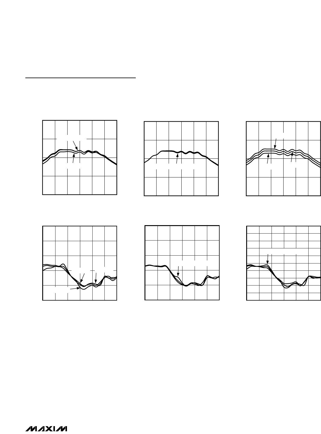
ranges is possible; see the Typical Operating
Characteristics for additional details.
This device can operate in high-side LO injection appli-
cations with an extended LO range, but performance
degrades as f
LO
continues to increase. See the Typical
Operating Characteristics for measurements taken with
f
LO
up to 2200MHz. For a device with better high-side
LO injection performance, contact the factory.
RF Port and Balun
For using the MAX2039 as a downconverter, the RF input
is internally matched to 50Ω, requiring no external match-
ing components. A DC-blocking capacitor is required
since the input is internally DC shorted to ground through
the on-chip balun. The RF return loss is typically 18dB
over the entire 1700MHz to 2200MHz RF frequency
range. For upconverter operation, the RF port is a single-
ended output similarly matched to 50Ω.
LO Inputs, Buffer, and Balun
The MAX2039 can be used for either high-side or low-
side injection applications with a 1500MHz to 2000MHz
LO frequency range. For a device with a 1900MHz to
2400MHz LO frequency range, contact the factory. As
an added feature, the MAX2039 includes an internal LO
SPDT switch that can be used for frequency-hopping
applications. The switch selects one of the two single-
ended LO ports, allowing the external oscillator to settle
on a particular frequency before it is switched in. LO
switching time is typically less than 50ns, which is more
than adequate for virtually all GSM applications.
High-Linearity, 1700MHz to 2200MHz Upconversion/
Downconversion Mixer with LO Buffer/Switch
12 ______________________________________________________________________________________
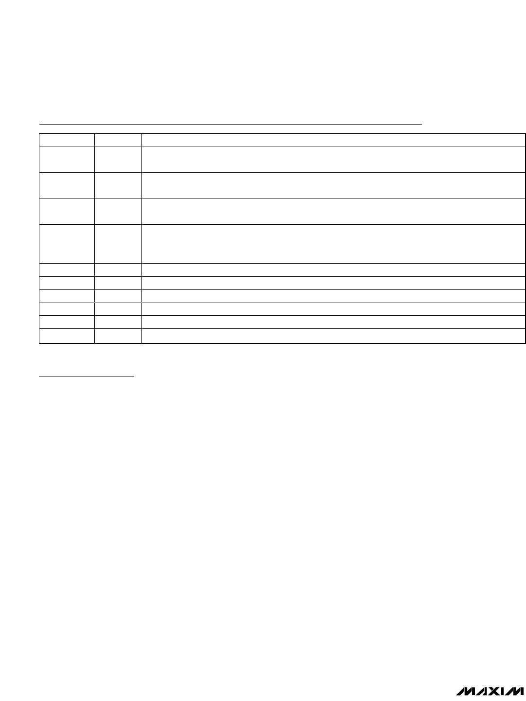
Pin Description