AP7312
DUAL 150mA LOW QUIESCENT CURRENT FAST
TRANSIENT LOW DROPOUT LINEAR REGULATOR
AP7312
Document number: DS35133 Rev. 2 - 2
12 of 18
www.diodes.com
January 2011
© Diodes Incorporated
NEW PRODUCT
Application Note
Input Capacitor
A 1μF ceramic capacitor is recommended between IN and GND pins to decouple input power supply glitch and noise. The
amount of the capacitance may be increased without limit. This input capacitor must be located as close as possible to the
device to assure input stability and reduce noise. For PCB layout, a wide copper trace is required for both IN and GND pins.
A lower ESR capacitor type allows the use of less capacitance, while higher ESR type requires more capacitance.
Output Capacitor
The output capacitor is required to stabilize and improve the transient response of the LDO. The AP7312 is stable with very
small ceramic output capacitors. Using a ceramic capacitor value that is at least 1μF with ESR≧10mΩ on the output ensures
stability. Higher capacitance values help to improve line and load transient response. The output capacitance may be
increased to keep low undershoot and overshoot. Output capacitor must be placed as close as possible to OUT and GND
pins.
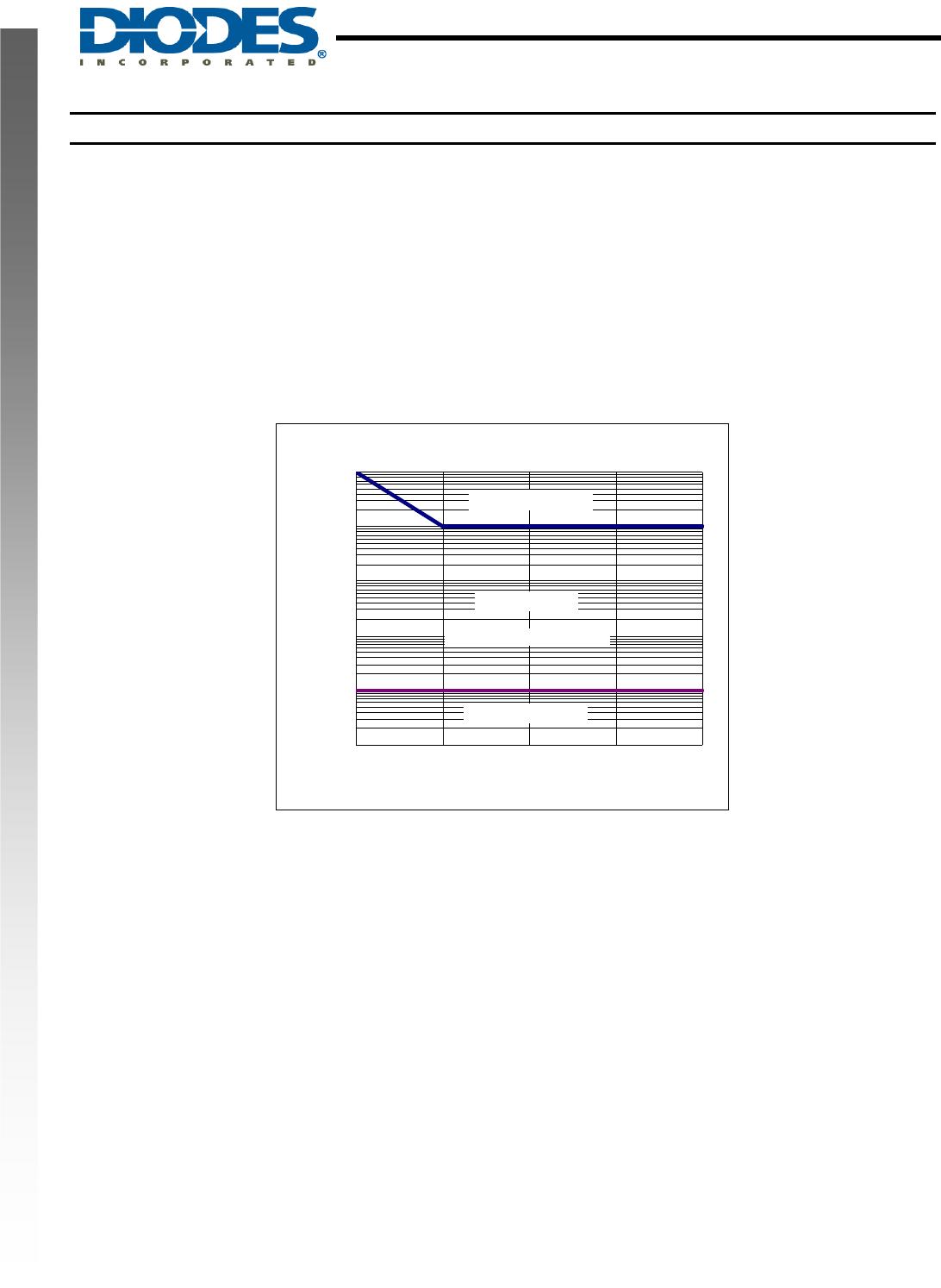
Region of Stable C
OUT
ESR vs. Load Current
0.001
0.01
0.1
1
10
100
0 20 50 100 150
Load Current (mA)
C
OUT
ESR (Ω)
No Load Stability
Other than external resistor divider, no minimum load is required to keep the device stable. The device will remain stable and
regulated in no load condition.
ON/OFF Input Operation
The AP7312 is turned on by setting the EN pin high, and is turned off by pulling it low. If this feature is not used, the EN pin
should be tied to IN pin to keep the regulator output on at all time. To ensure proper operation, the signal source used to drive
the EN pin must be able to swing above and below the specified turn-on/off voltage thresholds listed in the Electrical
Characteristics section under V
IL
and V
IH
.
Stable Range
Unstable Range
C
IN
=C
OUT1
= C
OUT2
=1μF
Unstable Range