6
Insulation and Safety Related Specications
Parameter Symbol Value Units Conditions
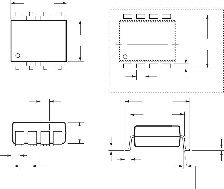
Min. External Clearance L(IO1) 9.6 mm Measured from input terminals to output
(External Air Gap) terminals, shortest distance through air
Min. External Creepage L(IO2) 10.0 mm Measured from input terminals to output
(External Tracking Path) terminals, shortest distance path along body
Min. Internal Clearance 1.0 mm Through insulation distance conductor to
(Internal Plastic Gap) conductor, usually the direct distance
between the photoemitter and photodetector
inside the optocoupler cavity
Min. Internal Creepage 4.0 mm The shortest distance around the border
(Internal Tracking Path) between two dierent insulating materials
measured between the emitter and detector
Comparative Tracking Index CTI 200 V DIN IEC 112/VDE 0303 PART 1
Isolation Group IIIa Material group (DIN VDE 0110)
Option 300 – surface mount classication is Class A in accordance with CECC 00802.
IEC/EN/DIN EN 60747-5-2 Insulation Characteristics (Option #050 Only)
Description Symbol Characteristic Unit
Installation classication per DIN VDE 0110/1.89, Table 1
For rated mains voltage ≤600 V rms I‑IV
For rated mains voltage ≤1000 V rms I‑III
Climatic Classication (DIN IEC 68 part 1) 55/100/21
Pollution Degree (DIN VDE 0110 Part 1/1.89) 2
Maximum Working Insulation Voltage V
IORM
1414 V
peak
Input to Output Test Voltage, Method b* V
PR
2651 V
peak
V
PR
= 1.875 x V
IORM
, 100% Production Test with
t
m
= 1 sec, Partial Discharge < 5 pC
Input to Output Test Voltage, Method a* V
PR
2121 V
peak
V
PR
= 1.5 x V
IORM
, Type and sample test, t
m
= 60 sec,
Partial Discharge < 5 pC
Highest Allowable Overvoltage* V
IOTM
8000 V
peak
(Transient Overvoltage, t
ini
= 10 sec)
Safety‑Limiting Values
(Maximum values allowed in the event of a failure,
also see Figure 11)
Case Temperature T
S
150 °C
Current (Input Current I
F
, P
S
= 0) I
S
400 mA
Output Power P
S,OUTPUT
700 mW
Insulation Resistance at T
S
, V
IO
= 500 V R
S
>10
9
Ω
*Refer to the front of the Optocoupler section of the current catalog for a more detailed description of IEC/EN/DIN EN 60747‑5‑2 and other prod‑
uct safety regulations.
Note: Optocouplers providing safe electrical separation per IEC/EN/DIN EN 60747‑5‑2 do so only within the safety‑limiting values to which they
are qualied. Protective cut‑out switches must be used to ensure that the safety limits are not exceeded.