Data Sheet AD9665
Rev. F | Page 9 of 16
APPLICATIONS INFORMATION
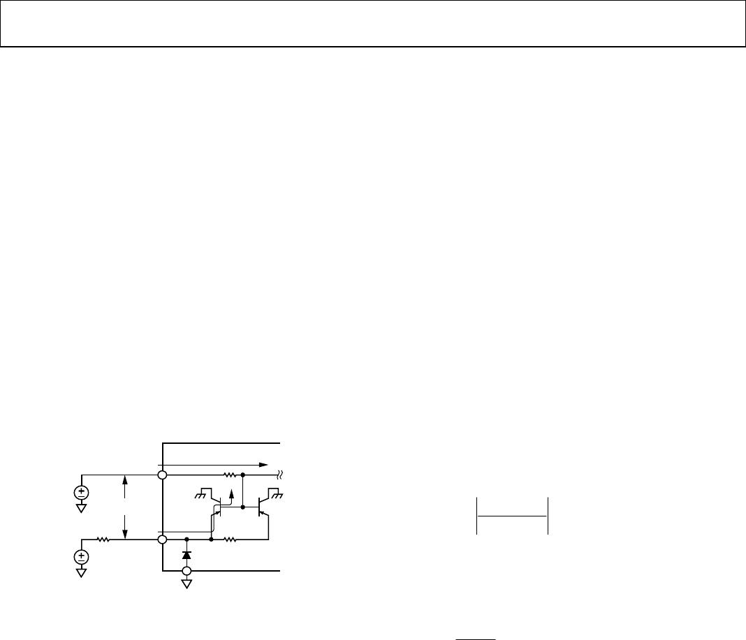
The AD9665 uses the current at one or more of its four inputs,
RSET, W1SET, W2SET, and W3SET, and generates an output
current proportional to the sum of the input currents. The read
channel has a typical gain of 105 mA/mA, Write Channel 1 has
a typical gain of 300 mA/mA, Write Channel 2 has a typical
gain of 200 mA/mA, and Write Channel 3 has a typical gain of
100 mA/mA. The input impedance of all the channels is
typically 200 Ω. In most cases, a voltage output DAC can be
used to drive these channels. In this case, a series resistance
should be placed between each of the DAC channels and the
respective input on the AD9665. These resistances should be
selected to scale the desired maximum output current for each
channel with an appropriate voltage from the DAC without
excessively loading it.
BOARD LAYOUT
Due to the fast rise and fall time (<1 ns) required for the
operation of high speed drives, trace lengths carrying high
speed signals, such as
RDIS
, W1DIS, W2DIS, and W3DIS, and
the output current should be kept as short as possible to
minimize series inductance. A decoupling capacitor should be
located near each V
DD
pin, and the ground return for the
cathode of the laser diode should be kept as short as possible.
An S11 measurement of a piece of flexible printed circuit board
(FPC) can show the inductance associated with that section of
the FPC. In Table 4, an S11 measurement of two different pieces
of a 19 mm (0.75 in) FPC was taken. The first piece is a single
layer of an FPC with 0.5 ounce copper and 25.4 micron (1 mil)
thick Kapton
® and coverlay. The second piece is an FPC with
2 layers of 0.5 ounce copper and 25.4 micron (1 mil) thick
Kapton and coverlay.
Table 4. Inductance of FPC
S11 L, nH @ 10 MHz L, nH @ 300 MHz
Single-layer FPC 8.8 8.5
Double-layer FPC 4.3 4.2
As indicated by the measurement results, using two layers of
copper in an FPC can reduce inductance by over 50%. Using the
basic circuit equation
d
t
di
LV
it can be seen that increasing the amplitude of a current step
increases the voltage drop across the inductor. For example, on
the single-layer FPC, a 200 mA pulse with a rise time of 1 ns
generates a voltage drop of 1.86 V, assuming an additional
0.5 nH of inductance due to the laser diode itself. Increase this
current to 250 mA, and the voltage drop is greater than 2.3 V.
Add this to the ~2 V of operating voltage that is required for the
laser diode, and voltage headroom can become a problem if
operating on a 5 V supply. Because the di/dt term seems to be a
system requirement, L is the only contributor that can be
changed when trying to reduce the voltage drop. Decreasing the
inductance of the FPC can be done by either making the trace
wider or by making it shorter. Because the distance from the
laser diode driver (LDD) to the laser diode is fixed, using a
wider trace is the only option. This can be accomplished by
changing from a single-layer FPC design to a double-layer FPC
design. This additional layer allows the full width of the FPC
from the LDD to the laser diode to be used for the drive
current, while the bottom layer can be used entirely for the
return path (see Figure 15).
LASER
DIODE
TOP
TRACE
BOTTOM
TRACE
SINGLE-LAYER
FPC
I
DIODE
I
D
I
O
DE
DOUBLE-LAYER
FPC
I
DIOD
E
I
DIODE
VIA
05269-016
Figure 15. Single-Layer and Double-Layer Flexible Printed Circuit Boards
TEMPERATURE CONSIDERATIONS
The AD9665 is available in a 32-lead LFCSP with an exposed
heat pad on top of the package. Using a 4-layer JEDEC standard
test board, the θ
JA
of this package was determined without any
external heat sink attached to the exposed pad. This board is
made of FR4, is 1.60 mm thick, and consists of four copper
layers. The two internal layers are solid copper (1 oz/in
2
or
0.35 mm thick). The two surface layers (containing the
component and back side traces) use 2 oz/in
2
(0.70 mm thick)
of copper. This method of construction yields a θ
JA
for the
AD9665 of approximately 110°C/W. An integrated circuit
dissipating 500 mW and packaged in an LFCSP, while operating
in an ambient environment of 85°C, would have an internal
junction temperature of approximately 140°C.
85°C + 0.5 W × 110°C/W = 140°C
This junction temperature is within the maximum
recommended operating junction temperature of 150°C. This
can be improved by attaching an external heat sink to the exposed
heat pad of the package. Of course, this is not a realistic method for
mounting a laser diode driver in an optical storage device.
In an actual application, the laser diode driver would most
likely be mounted to a flexible circuit board. The θ
JA
of a system
AD9665 Data Sheet
Rev. F | Page 10 of 16
is highly dependent on the board layout, material, and heat
sink. The user must consider these conditions carefully.
Some of the circuitry of the AD9665 can be used to monitor the
internal junction temperature.
The AD9665 uses a combination of diodes and transistors to
protect it from electrostatic discharge (ESD). All input pins have
a diode between them and ground, with the anode connected to
ground and the cathode connected to the particular input pin.
The base-emitter junction of a PNP transistor is used for ESD
protection for each pin to V
DD
. The collector is electrically
connected to the substrate of the die (see Figure 16). The base-
emitter junction of this transistor can be used to monitor the
internal die temperature of the IC.
Using a 10 V source at the enable pin to forward-bias the base-
emitter junction and a 1 MΩ resistor to limit the current, a
2-point measurement can be used to calculate the junction
temperature of the IC. Because the enable pin (ENABLE) needs
to be high for normal operation, the AD9665 can be operated
normally with the 10 V applied through the 1 MΩ resistor.
For this experiment, V1 and V2 were measured between the
ENABLE pin (Pin 16) and the closest V
DD
pin (Pin 17).
5V
10V
1M
V1, V2
+
V
DD
ENABLE
I
BE
GND
R
S
I
DD
AD9665
05269-017
Figure 16. Junction Temperature Measurement Circuit
The most important aspect of measuring junction temperature
on the AD9665 is that only one variable in the system is
changed at a time. In this case, the only variable is the amount
of power being dissipated by the AD9665. Therefore, the
ambient temperature should be held constant. For example, to
measure the junction temperature of the AD9665 while
operating at 60°C ambient, the ambient temperature must be
held constant for both the initial measurement, V1, and the
final measurement, V2. This is true because of the relationship
between temperature and V
BE
. For the process with which the
AD9665 is fabricated, the change in V
BE
(ΔV
BE
) is related to the
die temperature by −1.9 mV/°C (note the negative coefficient).
Therefore, die temperature is directly related to ambient
temperature and the power dissipated.
While the power to the AD9665 is disconnected, the AD9665
should be allowed to reach thermal equilibrium (at the desired
ambient temperature). With all channels turned off such that
I
OUT
= 0 mA, measure V1 as shown in Figure 16 (note the
polarity).
The second point of the 2-point measurement is obtained when
the AD9665 is operated under load, for example, while driving a
laser. Before taking the measurement, the AD9665 must be
allowed adequate time to reach a thermal equilibrium.
As seen in Figure 16, the AD9665 has a finite parasitic resistance
(R
S
) between V
DD
(Pin 17) and the base of the PNP transistor.
This resistance is typically 120 mΩ. Because the goal of the
experiment is to measure ΔV
BE
of the transistor, the voltage
drop across this resistance must be taken into account to get an
accurate representation of the actual ΔV
BE
. This voltage drop
varies depending on the output current of the AD9665
operating under load. Therefore, the actual supply current (I
DD
)
must be measured for each measurement.
V
DROP
= I
DD
× R
S
So the resulting ΔV
BE
can be found as
ΔV
BE
= (V2 + V
DROP2
) − (V1 + V
DROP1
)
For increasing temperature, this result should be negative.
From ΔV
BE
, the final junction temperature is determined by
CmV/1.9
Δ
BE
A
J
V
TT
From the resulting temperature rise in addition to the measured
power dissipation, the thermal resistance from the junction to
ambient can be calculated as
P
D
= V
DD
× I
DD
V
LOAD
× I
LOAD
D
A
J
P
TT
JA
θ
Data Sheet AD9665
Rev. F | Page 11 of 16
SHUTDOWN SUPPLY CURRENT VARIATION
The AD9665 defaults to TTL input mode when the ENABLE
pin is tied low (ENABLE = 0), regardless of the position of the
INS pin. Because of this, there can be additional supply current
due to the applied voltage on the read, write, or OSCEN enable
pins, the cause of which is an inverter located on the TTL input
ENABLE pins (see Figure 17).
05269-052
INPUT OUTPUT
+V
DD
GND
Figure 17. Inverter Circuit
Voltages close to GND or V
DD
are not sufficient to turn on
both transistors. However, as voltages vary from these extremes,
significant current can flow. Figure 18 shows how the power-
down current varies with voltage applied on the read, write, or
OSCEN enable pins.
Therefore, to ensure the lowest possible shutdown current,
the read, write, and OSCEN voltages should be tied to either
0 V or 5 V.
05269-053
TTL VOLTAGE ON READ AND WRITE CHANNELS (V)
POWER-DOWN SUPPLY CURRENT (mA)
0 0.5 1.0 1.5 2.0 2.5 3.0 3.5 4.0 4.5
0
16
12
8
4
5.0
VALID
TTL HIGH
VALID
TTL LOW
NONVALID
TTL REGION
CHIP DISABLED
Figure 18. Read and Write TTL Enable Voltage vs. Supply Current

AD9665ACPZ-REEL7

Mfr. #:
Manufacturer:
Analog Devices Inc.
Description:
Laser Drivers 4CH LVDS Dual-Output w/ Oscillator
Lifecycle:
New from this manufacturer.
Delivery:
DHL FedEx Ups TNT EMS
Payment:
T/T Paypal Visa MoneyGram Western Union

Products related to this Datasheet