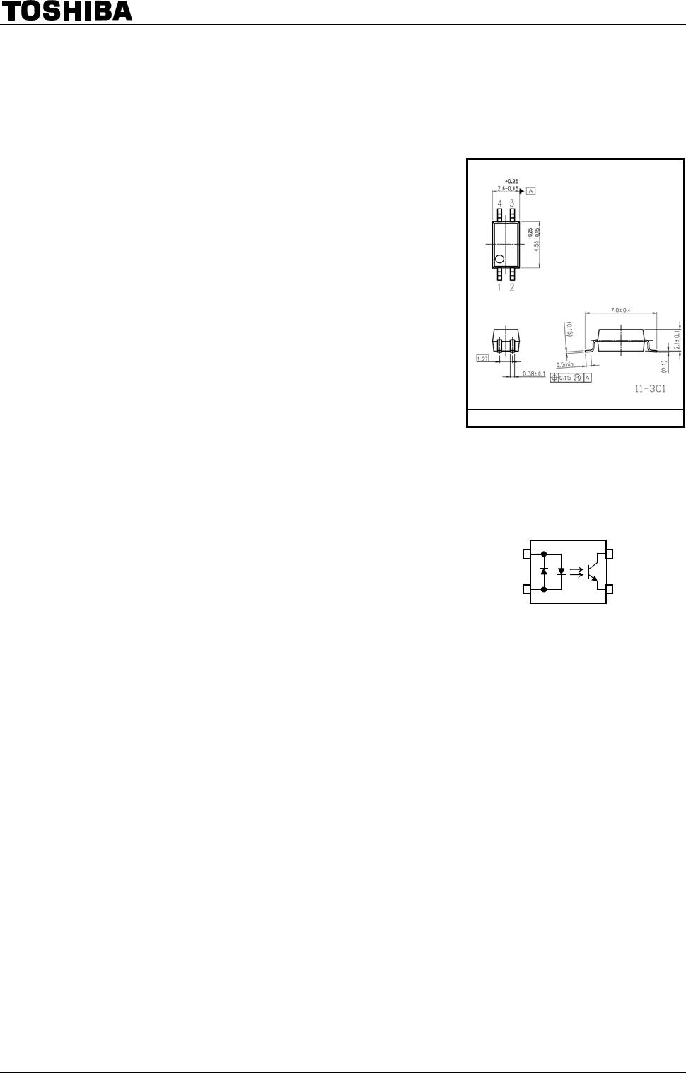
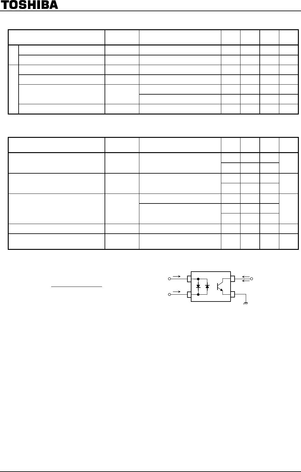
TLP290(TP,SE

TLP290(SE
TOSHIBA Photocoupler GaAs Ired & Photo-Transistor
TLP290(SE
Programmable Controllers
AC/DC-Input Module
Hybrid ICs
TLP290(SE consist of photo transistor, optically coupled to two gallium
arsenide infrared emitting diode connected inverse parallel, and can operate
directly by AC input current.
The TLP290(SE is housed in the very small and thin SO4 package.
Since TLP290(SE are guaranteed wide operating temperature (Ta=-55 to 110
˚C) and high isolation voltage (3750Vrms), it’s suitable for high-density
surface mounting applications such as programmable controllers and hybrid
ICs.
TOSHIBA 11-3C1
Weight: 0.05 g (typ.)
Unit: mm
Collector-Emitter voltage : 80 V (min)
Current transfer ratio : 50% (min)
Rank GB : 100% (min)
Isolation voltag
e : 3750 Vrms (min)
Guaranteed performance over -55 to 110 ˚C
UL recognized : UL1577, File No. E67349
32
41
TLP290
1: Anode
Cathode
2: Cathode
Anode
3: Emitter
4: Collector
Pin Configuration
cUL approve
d : CSA Component Acceptance Service No.5A,
File No. E67349
SEMKO conformity : EN 60065: 2002,
EN 60950-1: 2001, EN 60335-1: 2002,
BSI conformity : BS EN 60065: 2002, BS EN 60950-1: 2006,
VDE conformity : EN 60747-5-5
Construction Mechanical Rating
Creepage distance: 5.0 mm (min)
Clearance: 5.0 mm (min)
Insulation thickness: 0.4 mm (min)
2013-05-27
1
TLP290(SE
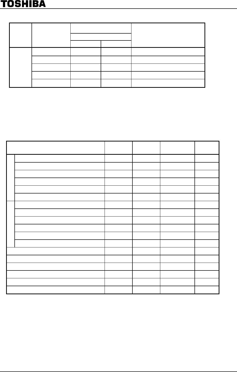
Current Transfer Ratio (Unless otherwise specified, Ta = 25°C)
Current Transfer Ration (%)
(I
C
/ I
F
)
I
F
= 5 mA, V
CE
= 5 V, Ta = 25°C
TYPE
Classification
(Note1)
Min Max
Marking of Classification
Blank 50 600
Blank, YE, GR, BL, GB
Rank Y 50 150 YE
Rank GR 100 300 GR
Rank GB 100 600 GB
TLP290
Rank BL 200 600 BL
Note1: Specify both the part number and a rank in this format when ordering
(e.g.) rank GB: TLP290(GB,SE
For safety standard certification, however, specify the part number alone.
(e.g.) TLP290(GB,SE: TLP290
Absolute Maximum Ratings (Note) (Unless otherwise specified, Ta = 25°C)
Characteristic Symbol
Note Rating
Unit
R.M.S. forward current I
F(RMS)
±50 mA
Input forward current derating (Ta 90°C) I
F
/Ta -1.5 mA /°C
Input forward current (pulsed) I
FP
(Note 2) ±1 A
Input power dissipation P
D
100 mW
Input power dissipation derating (Ta 90°C) P
D
/Ta -3.0 mW/°C
LED
Junction temperature T
j
125 °C
Collector-emitter voltage V
CEO
80 V
Emitter-collector voltage V
ECO
7 V
Collector current I
C
50 mA
Collector power dissipation P
C
150 mW
Collector power dissipation derating (Ta 25°C) P
C
/Ta -1.5 mW /°C
Detector
Junction temperature T
j
125 °C
Operating temperature range T
opr
-55 to 110 °C
Storage temperature range T
stg
-55 to 125 °C
Lead soldering temperature T
sol
260 (10s) °C
Total package power dissipation P
T
200 mW
Total package power dissipation derating (Ta 25°C) P
T
/Ta -2.0 mW /°C
Isolation voltage BV
S
(Note3) 3750
Vrms
Note: Using continuously under heavy loads (e.g. the application of high temperature/current/voltage and the
significant change in temperature, etc.) may cause this product to decrease in the reliability significantly even
if the operating conditions (i.e. operating temperature/current/voltage, etc.) are within the absolute maximum
ratings.
Please design the appropriate reliability upon reviewing the Toshiba Semiconductor Reliability Handbook
(“Handling Precautions”/“Derating Concept and Methods”) and individual reliability data (i.e. reliability test
report and estimated failure rate, etc).
Note2: Pulse width 100μs, frequency 100Hz
Note3: AC, 1min., R.H. 60%, Device considered a two terminal device: LED side pins shorted together and
detector side pins shorted together.
2013-05-27
2
TLP290(SE
2013-05-27
3
Electrical Characteristics (Unless otherwise specified, Ta = 25°C)
Characteristic Symbol Test Condition Min Typ Max Unit
Input forward voltage V
F
I
F
= ±10 mA 1.1 1.25 1.4 V
LED
Input capacitance C
T
V = 0 V, f = 1 MHz - 60 - pF
Collector-emitter breakdown voltage V
(BR) CEO
I
C
= 0.5 mA 80 - - V
Emitter-collector breakdown voltage V
(BR) ECO
I
E
= 0.1 mA 7 - - V
V
CE
= 48 V, - 0.01 0.08 μA
Dark current I
CEO
V
CE
= 48 V, Ta = 85°C - 2 50 μA
Detector
Collector-emitter capacitance C
CE
V = 0 V, f = 1 MHz - 10 - pF
Coupled Electrical Characteristics
(Unless otherwise specified, Ta = 25°C)
Characteristic Symbol Test Condition MIn Typ. Max Unit
50 - 600
Current transfer ratio I
C
/ I
F
I
F
= ±5 mA, V
CE
= 5 V
Rank GB
100 - 600
%
- 60 -
Saturated CTR I
C
/ I
F (sat)
IF = ±1 mA, V
CE
= 0.4 V
Rank GB
30 - -
%
I
C
= 2.4 mA, I
F
= ±8 mA - - 0.3
- 0.2 -
Collector-emitter
saturation voltage
V
CE (sat)
I
C
= 0.2 mA, I
F
= ±1 mA
Rank GB
- - 0.3
V
Off-state collector current I
C(off)
V
F
= ± 0.7 V, V
CE
= 48 V - - 10 μA
Collector current ratio I
C (ratio)
I
C
(I
F
= -5 mA) / I
C
(I
F
= 5 mA)
(Fig.1)
0.33 - 3 -
Fig.1: Collector current ratio test circuit
5V)
CE
V,
F1
I
F
(I
C1
I
5V)
CE
V,
F2
I
F
(I
C2
I
C(ratio)
I
V
CE
I
C1
I
C2
I
F1
I
F2

TLP290(TP,SE

Mfr. #:
Manufacturer:
Toshiba
Description:
Transistor Output Optocouplers 50mA Photocoupler 80V 50mA 3750Vrms
Lifecycle:
New from this manufacturer.
Delivery:
DHL FedEx Ups TNT EMS
Payment:
T/T Paypal Visa MoneyGram Western Union