LT3791
16
3791fb
For more information www.linear.com/LT3791
applicaTions inForMaTion
For high efficiency, choose an inductor with low core
loss. Also, the inductor should have low DC resistance to
reduce the I
2
R losses, and must be able to handle the peak
inductor current without saturating. To minimize radiated
noise, use a shielded inductor.
R
SENSE
Selection and Maximum Output Current
R
SENSE
is chosen based on the required output current. The
current comparator threshold sets the peak of the induc-
tor current
in boost operation and the maximum inductor
valley
current in buck operation. In boost operation, the
maximum average load current at V
IN(MIN)
is:
I
OUT(MAX _BOOST)
=
51mV
R
SENSE
ΔI
L
2
V
IN(MIN)
V
OUT
where ΔI
L
is peak-to-peak inductor ripple current. In buck
operation, the maximum average load current is:
I
OUT(MAX _BUCK )
=
47.5mV
R
SENSE
+
ΔI
L
2
The maximum current sensing R
SENSE
value for the boost
operation is:
R
SENSE(MAX)
=
2 51mV V
IN(MIN)
2I
LED
V
OUT
+ ΔI
L(BOOST)
V
IN(MIN)
The maximum current sensing R
SENSE
value for the buck
operation is:
R
SENSE(MAX)
=
2 47.5mV
2I
LED
ΔI
L(BUCK)
The final R
SENSE
value should be lower than the calculated
R
SENSE(MAX)
in both the boost and buck operation. A 20%
to 30% margin is usually recommended.
C
IN
and C
OUT
Selection
In boost operation, input current is continuous. In buck
operation, input current is discontinuous. In buck opera
-
tion, the selection of input capacitor, C
IN
, is driven by the
need to filter the input square wave current. Use a low ESR
capacitor sized to handle the maximum RMS current. For
buck operation, the input RMS current is given by:
I
RMS
= I
LED
2
D+
ΔI
L
2
12
D
BG1, BG2 DUTY CYCLE (%)
50
I
L
/I
SENSE(MAX)
(%)
120
160
200
90
3791 F07
80
40
100
140
180
60
20
0
6055
7065
80 85 95
75
100
BOOST I
L
/
I
SENSE(MAX)
LIMIT
BUCK I
L
/
I
SENSE(MAX)
LIMIT
Figure 7. Maximum Peak-to-Peak Ripple vs Duty Cycle
LT3791
17
3791fb
For more information www.linear.com/LT3791
Figure 8. Resistor Connection to Set V
IN
UVLO and
OVLO Thresholds
LT3791
V
IN
R1
R3
R4
R2
3791 F08
EN/UVLO
OVLO
The formula has a maximum at V
IN
= 2V
OUT
. Note that
ripple current ratings from capacitor manufacturers are
often based on only 2000 hours of life which makes it
advisable to derate the capacitor.
In boost operation, the discontinuous current shifts
from the input to the output, so C
OUT
must be capable
of reducing the output voltage ripple. The effects of ESR
(equivalent series resistance) and the bulk capacitance
must be considered when choosing the right capacitor
for a given output ripple voltage. The steady ripple due to
charging and discharging the bulk capacitance is given by:
ΔV
RIPPLE BOOST_CAP
( )
=
I
LED
V
OUT
V
IN(MIN)
( )
C
OUT
V
OUT
f
ΔV
RIPPLE BUCK _CAP
( )
ΔI
L
8 f C
OUT
where C
OUT
is the output filter capacitor.
The steady ripple due to the voltage drop across the ESR
is given by:
ΔV
BOOST(ESR)
= I
LED
ESR
ΔV
BUCK(ESR)
= I
LED
ESR
Multiple capacitors placed in parallel may be needed to
meet the ESR and RMS current handling requirements.
Output capacitors are also used for stability for the LT3791.
A good starting point for output capacitors is seen in the
Typical Applications circuits. Ceramic capacitors have
excellent low ESR characteristics but can have a high
voltage coefficient and are recommended for applications
less than 100W. Capacitors available with low ESR and
high ripple current ratings, such as OS-CON and POSCAP
may be needed for applications greater than 100W.
applicaTions inForMaTion
Programming V
IN
UVLO and OVLO
The falling UVLO value can be accurately set by the resistor
divider R1 and R2. A smallA pull-down current is active
when the EN/UVLO is below the threshold. The purpose
of this current is to allow the user to program the rising
hysteresis. The following equations should be used to
determine the resistor values:
V
IN(UVLO
)
= 1.2
R1+R2
R2
V
IN(UVLO
+
)
= 3µA R1+ 1.215
R1+R2
R2
The rising OVLO value can be accurately set by the resis-
tor divider R3 and R4. The following equations should be
used to determine the resistor values:
V
IN(OVLO
+
)
= 3
R3+ R4
R4
V
IN(OVLO
)
= 2.925
R3+ R4
R4
LT3791
18
3791fb
For more information www.linear.com/LT3791
applicaTions inForMaTion
Programming LED Current
The LED current is programmed by placing an appropriate
value current sense resistor, R
LED
, in series with the LED
string. The voltage drop across R
LED
is (Kelvin) sensed
by the ISP and ISN pins. The CTRL pin should be tied to
a voltage higher than 1.2V to get the full-scale 100mV
(typical) threshold across the sense resistor. The CTRL
pin can also be used to dim the LED current, although
relative accuracy decreases with the decreasing sense
threshold. When the CTRL pin voltage is less than 1V,
the LED current is:
I
LED
=
V
CTRL
200mV
R
LED
10
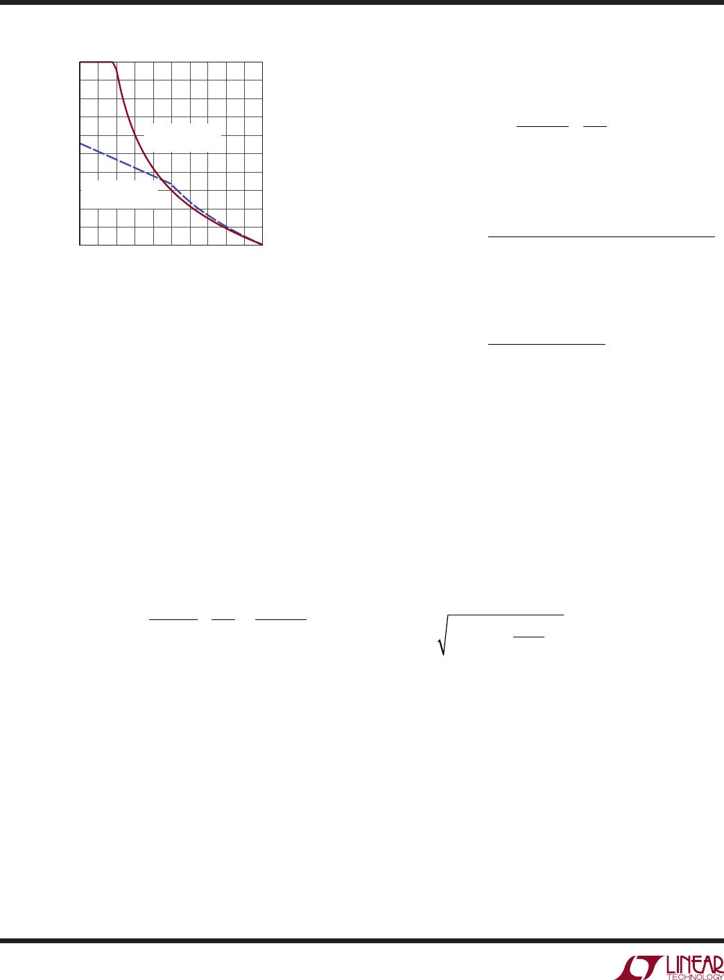
When the CTRL pin voltage is between 1.1V and 1.3V
the LED current varies with V
CTRL
, but departs from the
equation above by an increasing amount as V
CTRL
voltage
increases. Ultimately, when V
CTRL
> 1.3V the LED current
no longer varies. The typical V
(ISP-ISN)
threshold vs V
CTRL
is listed in Table 2.
Table 2. V
(ISP-ISN)
Threshold vs CTRL
V
CTRL
(V) V
(ISP-ISN)
(mV)
1.1 90
1.15 94.5
1.2 98
1.25 99.5
1.3 100
When V
CTRL
is higher than 1.3V, the LED current is
regulated to:
I
LED
=
100mV
R
LED
The CTRL pin should not be left open (tie to V
REF
if not
used). The CTRL pin can also be used in conjunction with
a thermistor to provide overtemperature protection for
the LED load, or with a resistor divider to V
IN
to reduce
output power and switching current when V
IN
is low.
The presence of a time varying differential voltage signal
(ripple) across ISP and ISN at the switching frequency
is expected. The amplitude of this signal is increased by
high LED load current, low switching frequency and/or a
smaller value output filter capacitor. Some level of ripple
signal is acceptable: the compensation capacitor on the
V
C
pin filters the signal so the average difference between
ISP and ISN is regulated to the user-programmed value.
Ripple voltage amplitude (peak-to-peak) in excess of
20mV should not cause mis-operation, but may lead to
noticeable offset between the average value and the user-
programmed value.
ISMON
The ISMON pin provides a linear indication of the cur
-
rent flowing
through the LEDs. The equation for V
ISMON
is V
(ISP–ISN)
• 10. This pin is suitable for driving an ADC
input, however, the output impedance of this pin is
12.5
so care must be taken not to load this pin.
Programming Input Current Limit
The LT3791 has a standalone current sense amplifier. It
can be used to limit the input current. The input current
limit is calculated by the following equation:
I
IN
=
50mV
R
IN

LT3791EFE#PBF

Mfr. #:
Manufacturer:
Analog Devices / Linear Technology
Description:
LED Lighting Drivers 60V 4-Switch Sync Buck-Boost LED Drvr Cn
Lifecycle:
New from this manufacturer.
Delivery:
DHL FedEx Ups TNT EMS
Payment:
T/T Paypal Visa MoneyGram Western Union