This is information on a product in full production.
High temperature 50 A SCRs
Datasheet - production data
Features
High junction temperature: T
j
= 150 °C
High noise immunity up to 150 °C
Gate triggering current I
GT
= 15 mA
Peak off-state voltage V
DRM
/V
RRM
= 600 V
High turn-on current rise dI/dt = 100 A/µs
ECOPACK
®
2 compliant component
Applications
Motorbike voltage regulator circuits
Inrush current limiting circuits
Motor control circuits and starters
Solid state relays
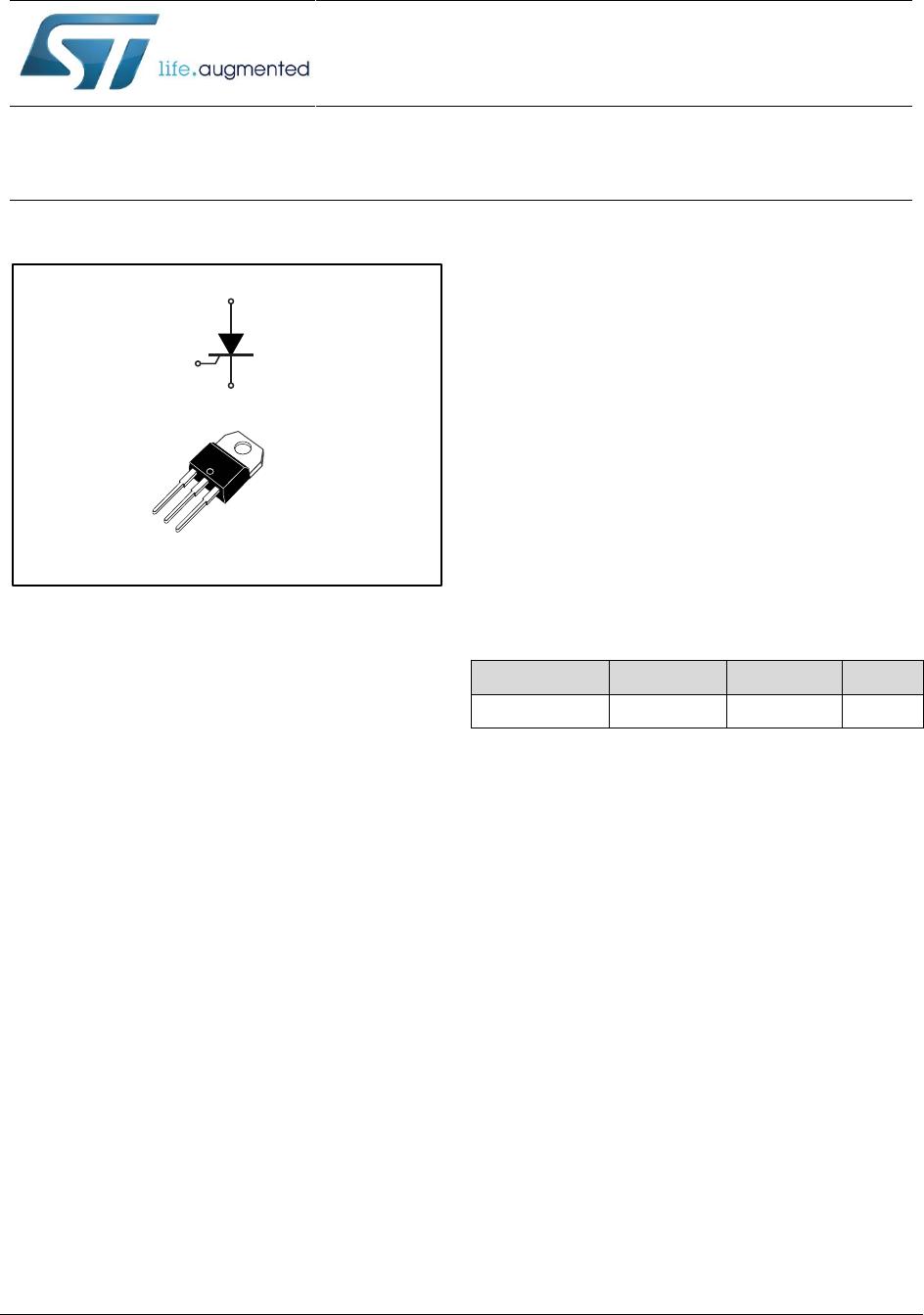
Description
Packaged in a non-isolated TO-220AB, this
device offers high thermal performance during
operation of up to 50 A, thanks to a junction
temperature of up to 150 °C.
Its noise immunity (dV/dt = 500 V/μs) trade-off
versus gate triggering current (I
GT
= 15 mA) and
its turn-on current rise (dI/dt = 100 A/μs) allow the
design of robust and compact control circuits for
voltage regulators in motorbikes and industrial
drives, overvoltage crowbar protection, motor
control circuits in power tools and kitchen
appliances, and inrush current-limiting circuits.
Table 1: Device summary

