Copyright Cirrus Logic, Inc. 2006–2015
(All Rights Reserved)
http://www.cirrus.com
98 dB, 96 kHz, Multi-Bit Audio A/D Converter
Features
Advanced Multi-Bit  Architecture
24-bit Conversion
Supports Audio Sample Rates Up to 108 kHz
98 dB Dynamic Range at 5 V
-92 dB THD+N at 5 V
Low-Latency Digital Filter
High-Pass Filter to Remove DC Offsets
Single +3.3 V or +5 V Power Supply
Power Consumption < 40 mW at 3.3 V
Master or Slave Operation
Slave Mode Speed Auto-Detect
Master Mode Default Settings
256x or 384x MCLK/LRCK Ratio
CS5343 Supports I²S Audio Format
CS5344 Supports Left-Justified Audio Format
General Description
The CS5343/4 is a complete analog-to-digital converter
for digital audio systems. It performs sampling, analog-
to-digital conversion, and anti-alias filtering, generating
24-bit values for both left and right inputs in serial form
at sample rates up to 108 kHz per channel.
The CS5343/4 uses a 3rd-order, multi-bit Delta-Sigma
modulator followed by a digital filter, which removes the
need for an external anti-alias filter.
The CS5343/4 also features a high-impedance sam-
pling network which eliminates costly external
components such as op-amps.
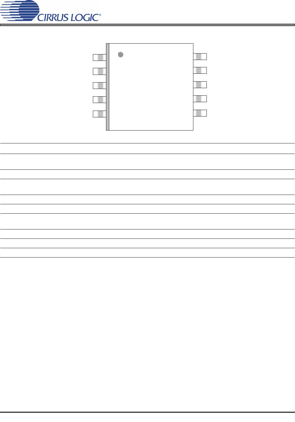
The CS5343/4 is available in a 10-pin TSSOP package
for both Commercial (-40° to +85° C) and Automotive
grades (-40° to +105° C). The CDB5343 Customer
Demonstration Board is also available for device evalu-
ation and implementation suggestions. Please refer to
the “Ordering Information” on page 19 for complete
details.
The CS5343/4 is ideal for audio systems requiring wide
dynamic range, negligible distortion and low noise, such
as set-top boxes, DVD-karaoke players, DVD record-
ers, A/V receivers, and automotive applications.
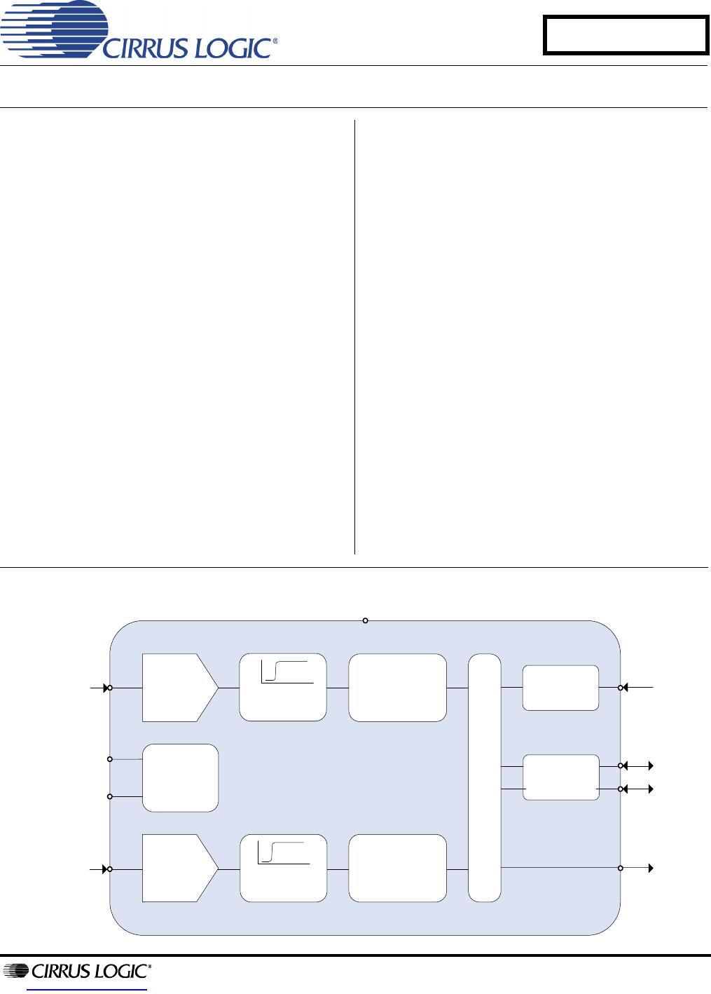
High-Pass
Filter
High-Pass
Filter
Low-Latency
Digital Filters
VA
3.3 V to 5 V
Internal
Reference
Voltages
High-Z
Sampling
Network
Auto-detect
MCLK Divider
Master
Clock
Single-Ended
Analog Input
Low-Latency
Digital Filters
High-Z
Sampling
Network
Single-Ended
Analog Input
SCLK
LRCK
SDOUT
FILT+
VQ
AINR
AINL
Serial Port
Slave Mode
Auto-detect
High-Pass
Filter
MAR '15
DS687F5
CS5343/4
Draft
3/10/15
2 DS687F5
CS5343/4
Draft
3/10/15
TABLE OF CONTENTS
1. PIN DESCRIPTIONS .............................................................................................................................. 3
2. CHARACTERISTICS AND SPECIFICATIONS ...................................................................................... 4
RECOMMENDED OPERATING CONDITIONS ..................................................................................... 4
ABSOLUTE MAXIMUM RATINGS ......................................................................................................... 4
ANALOG CHARACTERISTICS - COMMERCIAL GRADE (-CZZ) ......................................................... 5
ANALOG CHARACTERISTICS - AUTOMOTIVE GRADE (-DZZ) ......................................................... 6
DIGITAL FILTER CHARACTERISTICS ................................................................................................7
DC ELECTRICAL CHARACTERISTICS ................................................................................................ 7
DIGITAL CHARACTERISTICS ............................................................................................................... 8
SYSTEM CLOCKING AND SERIAL AUDIO INTERFACE ..................................................................... 9
3. TYPICAL CONNECTION DIAGRAM ................................................................................................... 11
4. APPLICATIONS ................................................................................................................................... 12
4.1 Operation as Clock Master or Slave ............................................................................................... 12
4.1.1 Slave Mode Operation ........................................................................................................... 12
4.1.2 Master Mode Operation ......................................................................................................... 13
4.1.2.1 Master Mode Speed Selection ................................................................................... 13
4.1.3 Master Clock ......................................................................................................................... 13
4.2 Serial Audio Interface ..................................................................................................................... 14
4.3 Digital Interface ............................................................................................................................... 14
4.4 Analog Connections ....................................................................................................................... 14
4.4.1 Component Values ................................................................................................................ 15
4.5 Grounding and Power Supply Decoupling ......................................................................................15
4.6 Synchronization of Multiple Devices ............................................................................................... 16
5. FILTER PLOTS - ALL SPEED MODES ............................................................................................... 16
6. PARAMETER DEFINITIONS ................................................................................................................ 17
7. PACKAGE DIMENSIONS .................................................................................................................... 18
THERMAL CHARACTERISTICS .......................................................................................................... 18
8. ORDERING INFORMATION ................................................................................................................ 19
9. REVISION HISTORY ............................................................................................................................ 20
DS687F5 3
CS5343/4
Draft
3/10/15
1. PIN DESCRIPTIONS
Pin Name Pin # Pin Description
SDOUT 1
Serial Audio Data Output (Output) - Output for two’s complement serial audio data. Also selects Master
or Slave Mode; See Section 4.1 on page 12 for details.
SCLK 2 Serial Clock (Input/Output) - Serial clock for the serial audio interface.
LRCK 3
Left Right Clock (Input/Output) - Determines which channel, Left or Right, is currently active on the
serial audio data line.
MCLK 4 Master Clock (Input) - Clock source for the delta-sigma modulator and digital filters.
FILT+ 5 Positive Voltage Reference (Output) - Positive reference voltage for the internal sampling circuits.
AINL
AINR
6
8
Analog Input (Input) - The full-scale analog input level is specified in the Analog Characteristics specifi-
cation table.
VQ 7 Quiescent Voltage (Output) - Filter connection for the internal quiescent reference voltage.
GND 9 Ground (Input) - Ground reference. Must be connected to analog ground.
VA 10 Power (Input) - Positive power supply for the digital and analog sections.
1
2
3
4
5
6
7
8
9
10
SDOUT
SCLK
LRCK
MCLK
FILT+
VA
GND
AINR
VQ
AINL

CS5343-CZZR

Mfr. #:
Manufacturer:
Cirrus Logic
Description:
Audio A/D Converter ICs IC 98dB 24-bit 96kHz Stereo ADC
Lifecycle:
New from this manufacturer.
Delivery:
DHL FedEx Ups TNT EMS
Payment:
T/T Paypal Visa MoneyGram Western Union

Products related to this Datasheet