LTC1044A
6
1044afa
For more information www.linear.com/LTC1044A
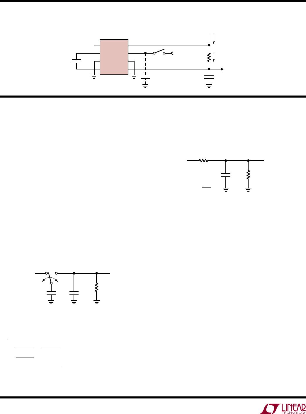
TesT circuiT
applicaTions inForMaTion
Theory of Operation
To understand the theory of operation of the LTC1044A,
a review of a basic switched-capacitor building block is
helpful.
In Figure 1, when the switch is in the left position, capaci
-
tor C
1 will charge to voltage V1. The total charge on C1
will
be q1 = C1V1. The switch then moves to the right,
discharging C1 to voltage V2. After this discharge time,
the charge on C1 is q2 = C1V2. Note that charge has been
transferred from the source, V1, to the output, V2. The
amount of charge transferred is:
∆q = q1 – q2 = C1(V1 – V2)
If the switch is cycled f times per second, the charge
transfer per unit time (i.e., current) is:
I = f • ∆q = f • C1(V1 – V2)
A new variable, R
EQUIV
, has been defined such that R
EQUIV
= 1/(f • C1). Thus, the equivalent circuit for the switched-
capacitor network is as shown in Figure 2.
Rewriting in terms of voltage and impedance equivalence,
=
1
(f •C1)
=
R
EQUIV
Figure 1. Switched-Capacitor Building Block
V1
1044a F01
V2
C1
f
C2
R
L
Examination of Figure 3 shows that the LTC1044A has the
same switching action as the basic switched-capacitor
building block. With the addition of finite switch-on
resistance and output voltage ripple, the simple theory
although not exact, provides an intuitive feel for how the
device works.
For example, if you examine power conversion efficiency
as a function of frequency (see typical curve), this simple
theory will explain how the LTC1044A behaves. The loss,
and hence the efficiency, is set by the output impedance.
As frequency is decreased, the output impedance will
eventually be dominated by the 1/(f • C1) term, and power
efficiency will drop. The typical curves for Power Efficiency
vs Frequency show this effect for various capacitor values.
Note also that power efficiency decreases as frequency
goes up. This is caused by internal switching losses which
occur due to some finite charge being lost on each switching
cycle. This charge loss per unit cycle, when multiplied by
the switching frequency, becomes a current loss. At high
frequency this loss becomes significant and the power
efficiency starts to decrease.
Figure 2. Switched-Capacitor Equivalent Circuit
V1
1044a F02
V2
C2
R
L
R
EQUIV
R
EQUIV
=
1
f × C1
1
2
3
4
8
7
6
5
LTC1044A
V
+
(5V)
+
C1
10µF
+
C2
10µF
C
OSC
V
OUT
R
L
I
S
I
L
EXTERNAL
OSCILLATOR
1044a TC

