This is information on a product in full production.
February 2017 DocID030200 Rev 1 1/14
ACST310-8B
Overvoltage protected AC switch
Datasheet production data
Features
AC switch with self over voltage protection
Microcontroller direct driven (low gate current
max. 10 mA)
Three quadrants (Q1, Q2 and Q3)
UL94-V0 certified resin (flammability)
ECOPACK
®
2 compliant component
Benefits
Enables equipment to meet IEC61000-4-5
High immunity against fast transients
described in IEC61000-4-4 standard
Needs no external overvoltage protection
High off-state reliability device
Interfaces directly with the microcontroller
Reduces component count
Applications
AC static switching in appliances and industrial
control systems
Driving low power highly inductive loads or
resistive AC loads, such as motor control
circuits, small home appliances, lighting, fan
speed controllers, water valves, pumps, solid
state relays, vacuum cleaners, heaters
Description
The ACST310-8B belongs to the ACS™ / ACST
power switch family built with A.S.D.
®
(application
specific discrete) technology. This high
performance device is suited to home appliances
or industrial systems and drives loads up to 3 A.
This ACST310-8B switch embeds a Triac
structure with a high voltage clamping device able
to absorb the inductive turn-off energy and
withstand line transients such as those described
in the IEC 61000-4-5 standard.The component
needs a low gate current to be activated (I
GT
max.
10 mA) and still shows a high electrical noise
immunity complying with IEC standards such as
IEC 61000-4-4 (fast transient burst test).
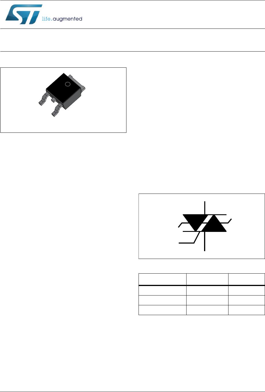
Figure 1. Functional diagram
ACS™, is a trademark of STMicroelectronics.
®
: A.S.D., ECOPACK are registered trademarks
of STMicroelectronics
&20
*
287
'3$.
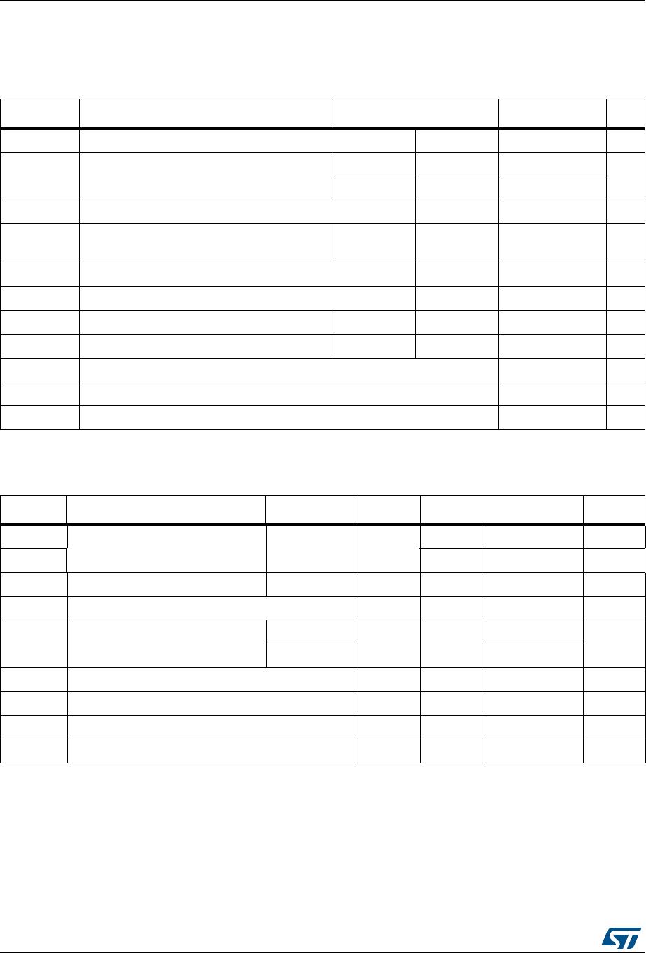
Table 1. Device summary
Symbol Value Unit
I
T(RMS)
3A
I
GT(Q1, Q2, Q3)
10 mA
V
DRM
/V
RRM
800 V
287
*$7(
&20
www.st.com
Characteristics ACST310-8B
2/14 DocID030200 Rev 1
1 Characteristics
Table 2. Absolute ratings (limiting values)
Symbol Parameter Test conditions Value Unit
I
T(RMS)
On-state RMS current (full sine wave) T
c
= 112 °C 3 A
I
TSM
Non repetitive surge peak on-state current
(T
j
initial = 25 °C)
f = 50 Hz t
p
= 20 ms 20
A
f = 60 Hz t
p
= 16.7 ms 21
I
2
tI
2
t value for fusing (T
j
initial = 25 °C) t
p
= 10 ms 2.6 A²s
dI/dt
Critical rate of rise of on-state current
I
G
= 2 x I
GT,
t
r
100 ns
f = 120 Hz T
j
= 125 °C 50 A/µs
V
PP
(1)
Non repetitive line peak mains voltage T
j
= 25 °C 2 kV
P
G(AV)
Average gate power dissipation T
j
= 125 °C 0.1 W
P
GM
Peak gate power t
p
= 20 µs T
j
= 125 °C 10 W
I
GM
Peak gate current t
p
= 20 µs T
j
= 125°C 1.6 A
T
stg
Storage junction temperature range -40 to +150 °C
T
j
Operating junction temperature range -40 to +125 °C
T
L
Maximum lead temperature for soldering during 10 s 260 °C
1. according to test described by IEC 61000-4-5 standard (see Figure 18).
Table 3. Electrical characteristics
Symbol Test conditions Quadrant T
j
Value Unit
I
GT
(1)
V
OUT
= 12 V, R
L
= 33 I - II - III 25 °C
Max. 10 mA
V
GT
Max. 1.1 V
V
GD
V
OUT
= V
DRM
, R
L
= 3.3 k I - II - III 125 °C Min. 0.2 V
I
H
(2)
I
OUT
= 100 mA 25 °C Max. 20 mA
I
L
I
G
= 1.2 x I
GT
I - III
25 °C Max.
25
mA
II 35
dV/dt
(2)
V
OUT
= 67% V
DRM
, gate open 125 °C Min. 1000 V/µs
(dI/dt)c
(2)
(dV/dt)c = 0.1V/µs 125 °C Min. 5 A/ms
(dI/dt)c
(2)
(dV/dt)c = 10 V/µs 125 °C Min. 1 A/ms
V
CL
(2)
I
CL
= 0.1 mA, tp = 1 ms 25 °C Min. 850 V
1. Minimum I
GT
is guaranteed at 5% of I
GT
max.
2. For both polarities of OUT pin referenced to COM pin
DocID030200 Rev 1 3/14
ACST310-8B Characteristics
14
Table 4. Static characteristics
Symbol Test conditions Value Unit
V
TM
(1)
I
TM
= 4.2 A, t
p
= 380 µs T
j
= 25 °C Max. 1.8 V
V
TO
(1)
Threshold voltage T
j
= 125 °C Max. 0.9 V
R
D
(1)
Dynamic resistance T
j
= 125 °C Max. 200 m
I
DRM
I
RRM
V
OUT
= V
DRM
/ V
RRM
T
j
= 25 °C
Max.
10
µA
T
j
= 125 °C 500
1. For both polarities of OUT pin referenced to COM pin
Table 5. Thermal resistances
Symbol Parameter Value Unit
R
th(j-c)
Junction to case (AC) 3 °C/W
R
th(j-a)
Junction to ambient S
Cu
(1)
= 0.5 cm² 70 °C/W
1. S
cu
= copper surface under tab
Figure 2. Maximum power dissipation versus
RMS on-state current (full cycle)
Figure 3. On-state RMS current versus case
temperature
3:






      
D 

,
7506
$
,
7506
$





    
7
F
&
Į 

ACST310-8B

Mfr. #:
Manufacturer:
STMicroelectronics
Description:
Triacs Overvoltage protected AC switch
Lifecycle:
New from this manufacturer.
Delivery:
DHL FedEx Ups TNT EMS
Payment:
T/T Paypal Visa MoneyGram Western Union

Products related to this Datasheet