DocID030200 Rev 1 9/14
ACST310-8B Application information
14
2.2 AC line transient voltage ruggedness
In comparison with standard Triacs, which are not robust against surge voltage, the
ACST310-8B is self-protected against over-voltage, specified by the parameter V
CL
. In
addition, the ACST310-8B is a sensitive device (I
GT
max. 10 mA), but provides a high noise
immunity level against fast transients. The ACST310-8B switch can safely withstand AC line
transient voltages either by clamping the low energy spikes, such as inductive spikes at
switch off, or by switching to the on state (for less than 10 ms) to dissipate higher energy
shocks through the load. This safety feature works even with high turn-on current ramp up.
The test circuit of Figure 18 represents the ACST310-8B application, and is used to stress
the ACST310-8B switch according to the IEC 61000-4-5 standard conditions. With the
additional effect of the load which is limiting the current, the ACST310-8B switch withstands
the voltage spikes up to 2 kV on top of the peak line voltage. The protection is based on an
overvoltage crowbar technology. The ACST310-8B folds back safely to the on state as
shown in Figure 19. The ACST310-8B recovers its blocking voltage capability after the
surge and the next zero current crossing. Such a non-repetitive test can be done at least 10
times on each AC line voltage polarity.
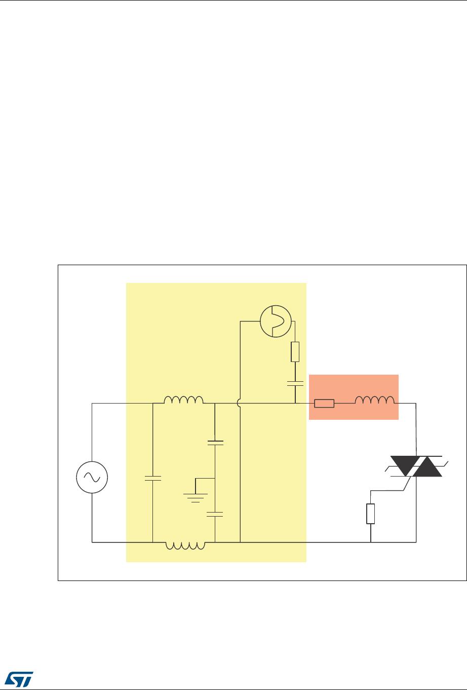
Figure 18. Overvoltage ruggedness test circuit for resistive and inductive loads for
IEC 61000-4-5 standards
1. R = 30 Ω, L = 10 µH, V
pp
= 2 kV (Surge Generator), Rg = 220 Ω, AC mains = 230 V
RMS
50 Hz
287
&20
*$7(
)LOWHULQJXQLW
$&PDLQV
5JHQHUDWRU
0RGHORIWKHORDG
/
5
5J
6XUJHJHQHUDWRU
&F