INA226AQDGSRQ1

NSIC2020JBT3G
http://onsemi.com
4
TYPICAL PERFORMANCE CURVES
(Minimum FR−4 @ 100 mm
2
, 1 oz. Copper Trace, Still Air)
−0.040 mA/°C
Figure 2. Steady State Current (I
reg(SS)
) vs.
Anode−Cathode Voltage (Vak)
Figure 3. Pulse Current (I
reg(P)
) vs.
Anode−Cathode Voltage (Vak)
Figure 4. Steady State Current vs. Pulse
Current Testing
Vak, ANODE−CATHODE VOLTAGE (V)
I
reg(P)
, PULSE CURRENT (mA)
Figure 5. Current Regulation vs. Time
TIME (s)
60504020100
21.0
I
reg
, REGULATION CURRENT (mA)
30 80
19.8
20.2
Figure 6. Power Dissipation vs. Ambient
Temperature @ T
J
= 1755C: Small Footprint
T
A
, AMBIENT TEMPERATURE (°C)
P
D
, POWER DISSIPATION (mW)
20.4
20.6
20.8
Vak, ANODE−CATHODE VOLTAGE (V)
96543
5
15
20
25
I
reg(SS)
, STEADY STATE CURRENT (mA)
710
DC Test Steady State, Still Air
8
10
210
30
0
11 12 13 14 15
10987654
15
17
18
252221
17
18
I
reg(P)
, PULSE CURRENT (mA)
I
reg(SS)
, STEADY STATE CURRENT (mA)
16
19
20
3
19
20
21
22
23
21
23
21
T
A
= 25°C
Non−Repetitive Pulse Test
11 12 13 14 15
18 2317 2019
Vak @ 7.5 V
T
A
= 25°C
Vak @ 7.5 V
T
A
= 25°C
22
24
20.0
T
A
= −55°C
T
A
= 25°C
T
A
= 85°C
−0.066 mA/°C
T
A
= 125°C
8060200−20−40
500
1000
2000
2500
40
500 mm
2
/2 oz
300 mm
2
/1 oz
100 mm
2
/2 oz
1500
3000
0
100 mm
2
/1 oz
500 mm
2
/1 oz
300 mm
2
/2 oz
120100
T
J(max)
, maximum die temperature
limit 175°C (100 mm
2
, 1 oz Cu)
−0.045 mA/°C
70
FR−4 Board
T
A
= 150°C
Figure 7. Power Dissipation vs. Ambient
Temperature @ T
J
= 1755C: Large Footprint
T
A
, AMBIENT TEMPERATURE (°C)
8060200−20−40
500
1000
2000
2500
POWER DISSIPATION (mW)
40
DENKA K1, 900 mm
2
/2 oz
FR−4, 700 mm
2
/2 oz
1500
3000
0
FR−4, 1000 mm
2
/3 oz
3500
4000
4500
120100
DENKA K1, 400 mm
2
/2 oz
FR−4, 700 mm
2
/1 oz
NSIC2020JBT3G
http://onsemi.com
5
APPLICATIONS INFORMATION
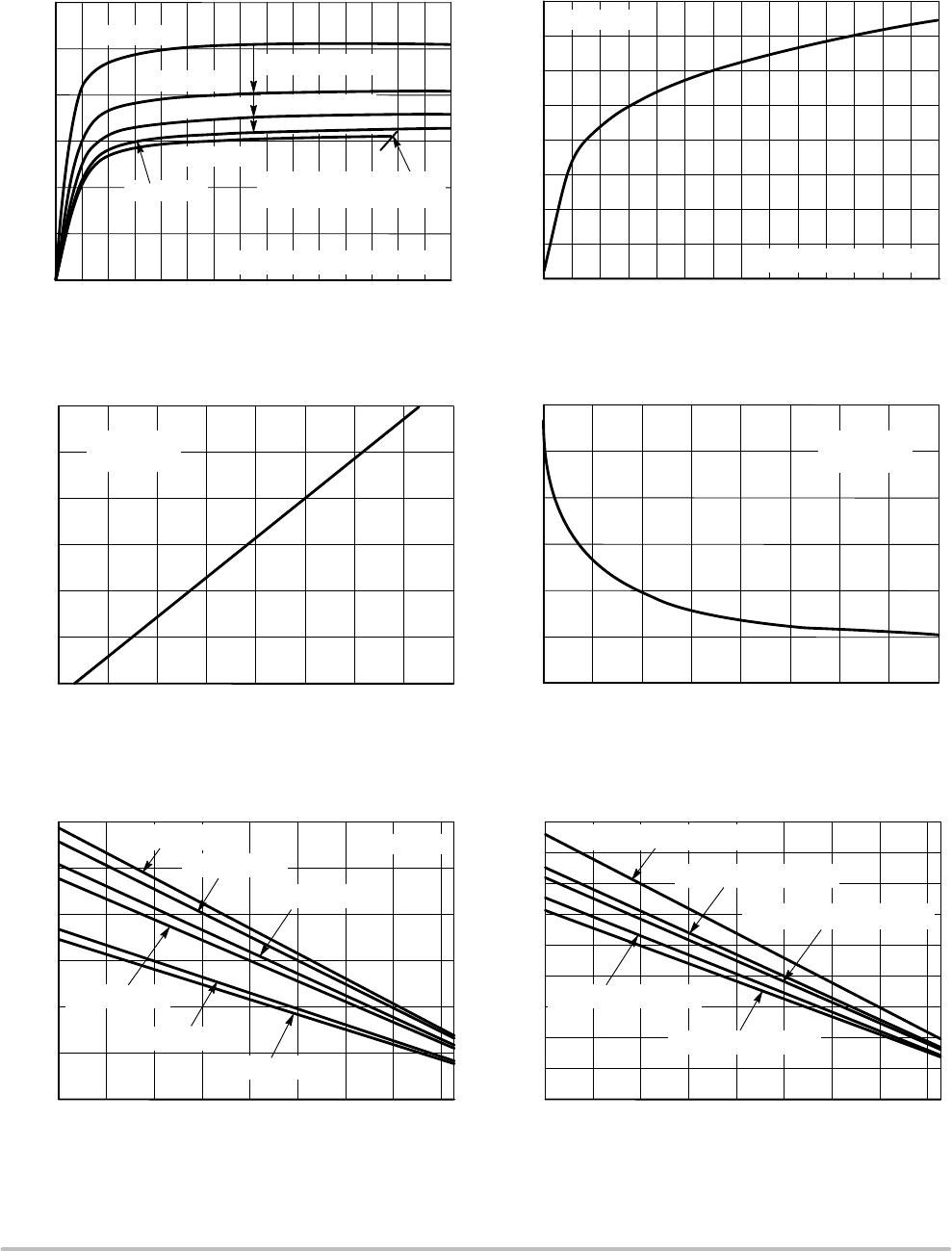
The CCR is a self biased transistor designed to regulate the
current through itself and any devices in series with it. The
device has a slight negative temperature coefficient, as
shown in Figure 2 – Tri Temp. (i.e. if the temperature
increases the current will decrease). This negative
temperature coefficient will protect the LEDS by reducing
the current as temperature rises.
The CCR turns on immediately and is typically at 20% of
regulation with only 0.5 V across it.
The device is capable of handling voltage for short
durations of up to 120 V so long as the die temperature does
not exceed 175°C. The determination will depend on the
thermal pad it is mounted on, the ambient temperature, the
pulse duration, pulse shape and repetition.
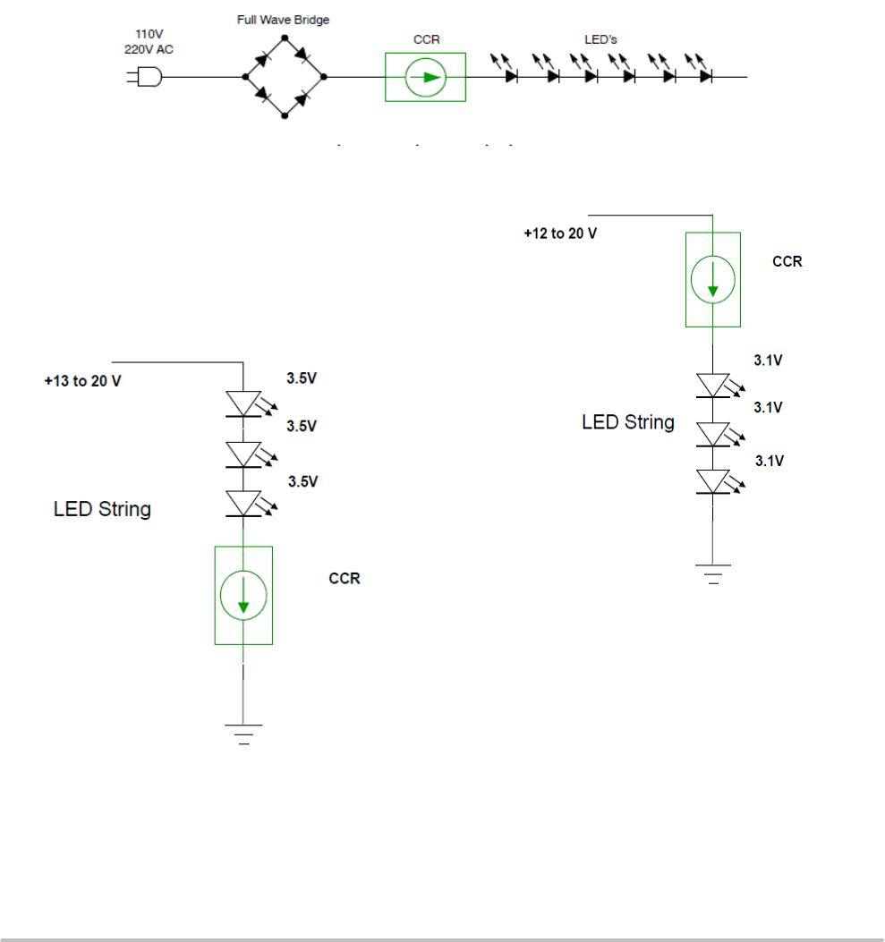
AC Applications
The CCR is a DC device; however, it can be used with full
wave rectified AC as shown in application notes
AND8433/D and AND8492/D and design notes
DN05013/D and DN06065/D. Figure 8 shows the basic
circuit configuration.
Figure 8. Basic AC Application
Single LED String
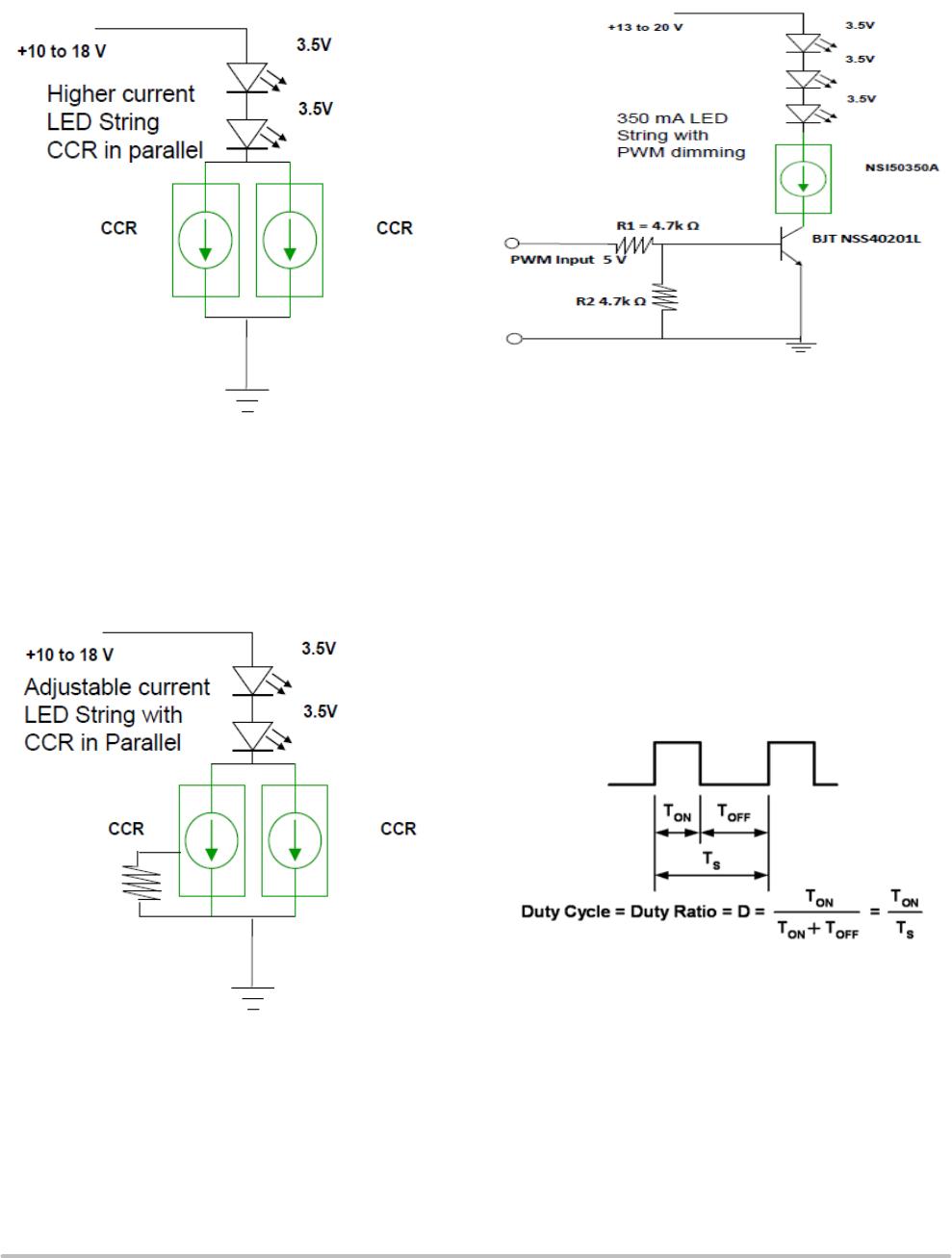
The CCR can be placed in series with LEDs as a High Side
or a Low Side Driver. The number of the LEDs can vary
from one to an unlimited number. The designer needs to
calculate the maximum voltage across the CCR by taking the
maximum input voltage less the voltage across the LED
string (Figures 9 and 10).
Figure 9.
Figure 10.
NSIC2020JBT3G
http://onsemi.com
6
Higher Current LED Strings
Two or more fixed current CCRs can be connected in
parallel. The current through them is additive (Figure 11).
Figure 11.
Other Currents
The adjustable CCR can be placed in parallel with any
other CCR to obtain a desired current. The adjustable CCR
provides the ability to adjust the current as LED efficiency
increases to obtain the same light output (Figure 12).
Figure 12.
Dimming using PWM
The dimming of an LED string can be easily achieved by
placing a BJT in series with the CCR (Figure 13).
Figure 13.
The method of pulsing the current through the LEDs is
known as Pulse Width Modulation (PWM) and has become
the preferred method of changing the light level. LEDs being
a silicon device, turn on and off rapidly in response to the
current through them being turned on and off. The switching
time is in the order of 100 nanoseconds, this equates to a
maximum frequency of 10 Mhz, and applications will
typically operate from a 100 Hz to 100 kHz. Below 100 Hz
the human eye will detect a flicker from the light emitted
from the LEDs. Between 500 Hz and 20 kHz the circuit may
generate audible sound. Dimming is achieved by turning the
LEDs on and off for a portion of a single cycle. This on/off
cycle is called the Duty cycle (D) and is expressed by the
amount of time the LEDs are on (Ton) divided by the total
time of an on/off cycle (Ts) (Figure 14).
Figure 14.

INA226AQDGSRQ1

Mfr. #:
Manufacturer:
Texas Instruments
Description:
Current & Power Monitors & Regulators AEC-Q100, 36V, Bi-Directional, High Accuracy, Low-/High-Side, I2C Out Current/Power Monitor w/Alert 10-VSSOP -40 to 125
Lifecycle:
New from this manufacturer.
Delivery:
DHL FedEx Ups TNT EMS
Payment:
T/T Paypal Visa MoneyGram Western Union

Products related to this Datasheet