MAX8901A/MAX8901B
Highest Efficiency Supply for 2 to 6
Series WLEDs in a 2mm x 2mm TDFN Package
_______________________________________________________________________________________ 7
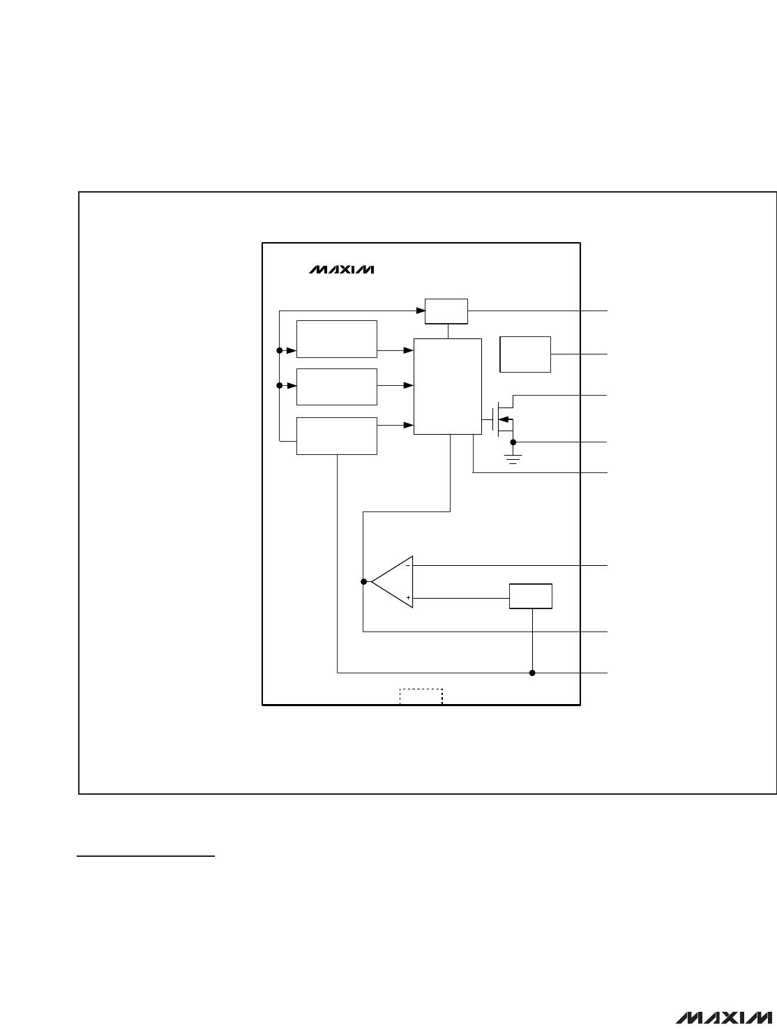
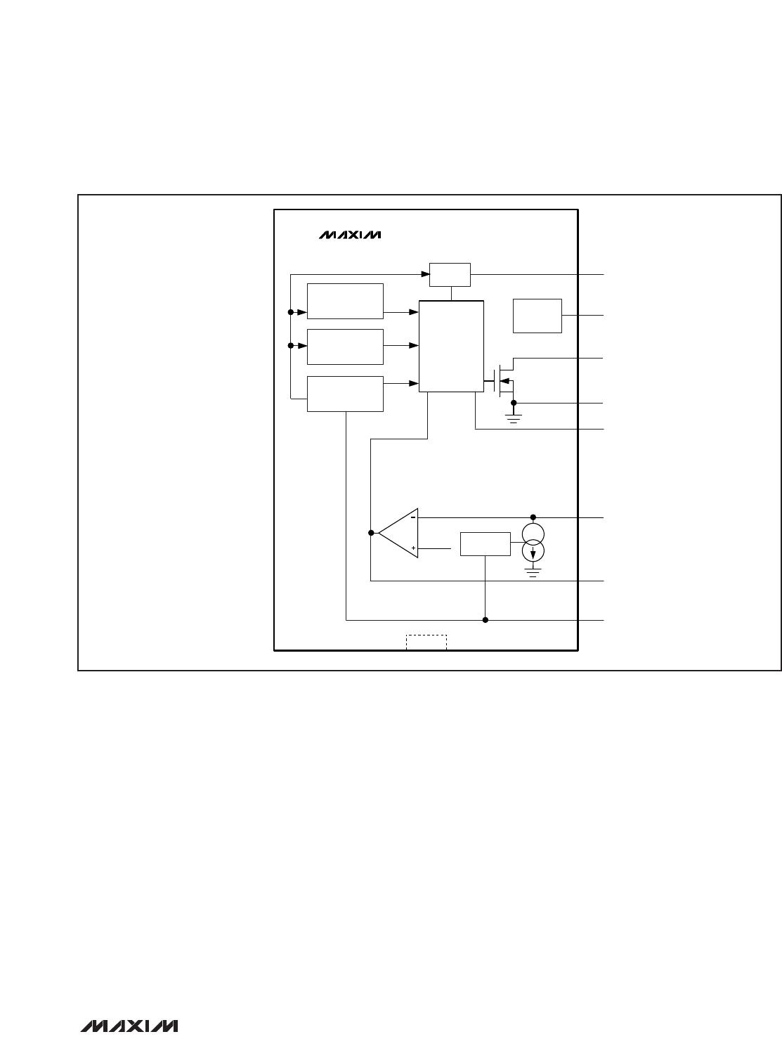
Pin Description
PIN NAME FUNCTION
1 OVP
WLED Overvoltage Protection Input. OVP monitors voltage at the WLEDs. Connect OVP to the
positive terminal of the output capacitor. If an OVP condition is detected, the MAX8901_ latch off.
Cycle V
IN
or toggle V
ON
to restart the IC.
2ON
Enable and Dimming Control Input. Drive ON high to enable the IC. Drive ON low for greater than
1.33ms (typ) to shutdown the WLED current regulator.
For the MAX8901A: After V
IN
is above V
UVLO
and ON is driven high, the MAX8901A enters soft-start
and increases the WLED current to full brightness. Apply a minimum 30kHz (500kHz max) PWM
signal to ON to adjust the WLED brightness from 100% to off, proportional to the duty cycle of the
PWM signal. See the PWM Dimming Control (MAX8901A) section for more details.
For the MAX8901B: After ON is driven high for 40µs (min), the MAX8901B enters soft-start and
increases the WLED current to full brightness. Subsequent pulses on ON cause the MAX8901B
WLED current to decrease in 32 equal steps. See the Serial-Pulse Dimming Control (MAX8901B)
section for more details.
3IN
Power Supply Input. Bypass IN to GND with a 1µF ceramic capacitor placed as close as possible to
the IC. If V
IN
exceeds the input overvoltage lockout threshold (6.5V max, V
IN
rising), the IC stops
switching and no WLED current flows (if the forward voltage of the WLED string is greater than V
IN
).
When V
IN
falls below the overvoltage lockout hysteresis level (6.0V min, V
IN
falling), soft-start is
initiated and normal operation resumes.
4 LX Boost Inductor Node. Connect an inductor between IN and LX. LX is high impedance in shutdown.
5 PGND Power Ground. Connect to GND and the exposed paddle (EP) with a short, wide trace.
6 GND Analog Ground. Connect GND to the exposed paddle with a short, wide trace.
7 COMP
WLED Boost Compensation Node. Connect a 0.022µF ceramic capacitor from COMP to GND.
C
COMP
stabilizes the converter and sets the soft-start time. COMP discharges to GND when in
shutdown.
8CS
WLED Current Sense Input. For the MAX8901A, connect a current-sense resistor from CS to GND.
Voltage sensed at CS regulates the WLED current. For the MAX8901B, do not connect a sense
resistor from CS to GND. The MAX8901B provides an internal current source from CS to GND to
program the WLED current. The MAX8901B regulates V
CS
to 0.5V (typ) for all I
LED.
The MAX8901A
regulates V
CS
to 0.5V (typ) for maximum duty cycle only.
—EP
Exposed Metal Paddle. Connect EP to GND. For good thermal dissipation, the exposed paddle must
be connected to a large ground plane.