©2011 Silicon Storage Technology, Inc. DS25080A 11/11
8
2 Mbit SPI Serial Flash
SST25LF020A
Not Recommended for New Designs
Microchip Technology Company
Write Enable Latch (WEL)
The Write-Enable-Latch bit indicates the status of the internal memory Write Enable Latch. If the
Write-Enable-Latch bit is set to “1”, it indicates the device is Write enabled. If the bit is set to “0” (reset),
it indicates the device is not Write enabled and does not accept any memory Write (Program/Erase)
commands. The Write-Enable-Latch bit is automatically reset under the following conditions:
• Power-up
• Write-Disable (WRDI) instruction completion
• Byte-Program instruction completion
• Auto Address Increment (AAI) programming reached its highest memory address
• Sector-Erase instruction completion
• Block-Erase instruction completion
• Chip-Erase instruction completion
Block Protection (BP1, BP0)
The Block-Protection (BP1, BP0) bits define the size of the memory area, as defined in Table 4, to be
software protected against any memory Write (Program or Erase) operations. The Write-Status-Regis-
ter (WRSR) instruction is used to program the BP1 and BP0 bits as long as WP# is high or the Block-
Protect-Lock (BPL) bit is 0. Chip-Erase can only be executed if Block-Protection bits are both 0. After
power-up, BP1 and BP0 are set to 1.
Block Protection Lock-Down (BPL)
WP# pin driven low (V
IL
), enables the Block-Protection-Lock-Down (BPL) bit. When BPL is set to 1, it
prevents any further alteration of the BPL, BP1, and BP0 bits. When the WP# pin is driven high (V
IH
),
the BPL bit has no effect and its value is “Don’t Care”. After power-up, the BPL bit is reset to 0.
Auto Address Increment (AAI)
The Auto Address Increment Programming-Status bit provides status on whether the device is in AAI
programming mode or Byte-Program mode. The default at power up is Byte-Program mode.
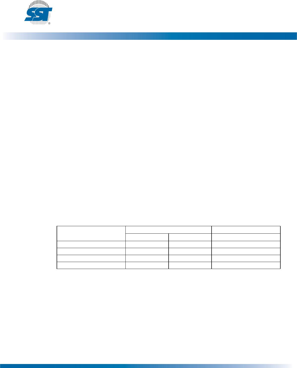
Table 4: Software Status Register Block Protection
1
1. Default at power-up for BP1 and BP0 is ‘11’.
Protection Level
Status Register Bit Protected Memory Area
BP1 BP0 2 Mbit
0 0 0 None
1 (1/4 Memory Array) 0 1 030000H-03FFFFH
2 (1/2 Memory Array) 1 0 020000H-03FFFFH
3 (Full Memory Array) 1 1 000000H-03FFFFH
T4.0 25080