PF2512FKF7W0R05L

Chip Resistor Surface Mount
w
ww.yageo.com
Nov 01, 2011 V.0
Product specification
4
10
SERIES
PR/PF/PH
0805/1206/2512/0815
MARKING
PF0805 / PH0805
No marking
PF1206 / PH1206 / PR2512: Full range
PF2512: R < 20 m
& R 20 m
with 2W
4 digits with top bar
The “R” is used as a decimal point; the other 3 digits are significant
PF2512: R 20 m
with 1W
4 digits
The “R” is used as a decimal point; the other 3 digits are significant
PF0815
4 digits: E24 series
The “R” is used as a decimal point; the other 3 digits are significant
For further marking information, please refer to data sheet “Chip resistors marking”.
Fig. 2 Value = 5 m
ynsc01
6
Fig. 3 Value = 20 m
YNSC00
5
020
Fig. 4 Value = 10 m
YNSC10
6
Fig. 1
ynsc10
7
Chip Resistor Surface Mount
w
ww.yageo.com
Nov 01, 2011 V.0
Product specification
5
10
SERIES
PR/PF/PH
0805/1206/2512/0815
CONSTRUCTION
The resistors are constructed using outstanding TCR level material, which makes Yageo PR/PF/PH resistors
excellent for current sensing application in battery charger circuit & DC-DC converter.
The composition of the resistive material is adjusted to give the approximate required resistance and is
covered with a protective coating, which printed with the resistance value.
Finally, the three external terminations (Cu / Ni / matte Tin) are added, as shown in Fig. 4.
H
W
I
1
protective coat
marking
L
I
2
end termination
metal substrate
protective coat
end termination
001
I
1
I
2
H
W
marking layer
protective coat
inner electrode
protective coat
resistive layer 
(metal foil)
ceramic substrate
L
0 0
end termination
I
1
I
2
W
H
L
YNSC105
marking layer
protective coat
inner electrode
protective coat
resistive layer (metal foil)
ceramic substrate
0 0
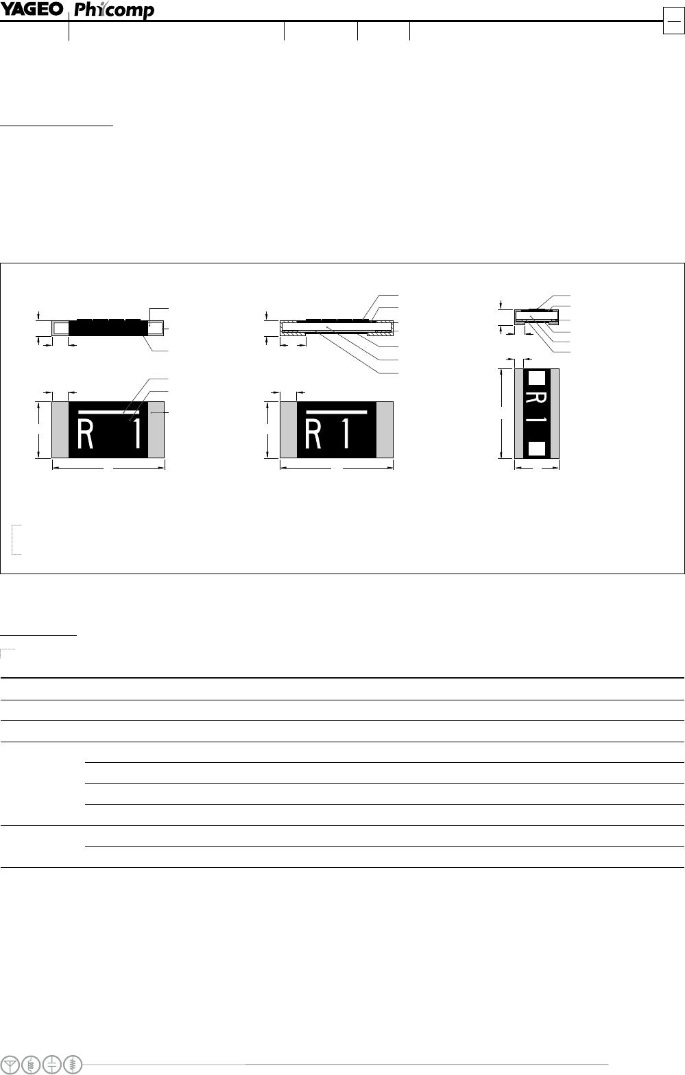
Fig. 5 Chip resistor outlines
O
O
u
u
t
t
l
l
i
i
n
n
e
e
s
s
For dimensions, please refer to Table 1
PR series PF / PH series
Note: construction will be adjusted to
resistance value
(
onl
for PF series
)
.
PF 0815 series
TYPE RESISTANCE RANGE L (mm) W (mm) H (mm) I
1
(mm) I
2
(mm)
PF/PH0805
0.01 to 0.05 2.03 ±0.25 1.27 ±0.25 0.33 ±0.12 0.38 ±0.25 0.38 ±0.25
PF/PH1206
0.01 to 0.05 3.20 ±0.25 1.60 ±0.25 0.60 ±0.25 0.50 ±0.25 0.65 ±0.25
PF0815
0.01 to 0.02 2.15 ±0.20 3.75 ±0.25 0.65 ±0.25 0.65 ±0.25 0.70 ±0.25
0.006 6.45 ±0.25 3.25 ±0.25 0.70 ±0.25 0.75 ±0.25 1.85 ±0.25
0.007 to 0.015 6.45 ±0.25 3.25 ±0.25 0.70 ±0.25 0.75 ±0.25 1.55 ±0.25
0.02 to 0.05 (1W) 6.45 ±0.25 3.25 ±0.25 0.70 ±0.25 1.30 ±0.25 0.75 ±0.25
PF2512
0.02 to 0.05 (2W) 6.45 ±0.25 3.25 ±0.25 0.70 ±0.25 0.75 ±0.25 1.30 ±0.25
0.001 to 0.002 6.40 ±0.20 3.20 ±0.20 0.75 ±0.15 1.20 ±0.20 1.20 ±0.20
PR2512
0.003 to 0.005 6.40 ±0.20 3.20 ±0.20 0.55 ±0.15 0.60 ±0.20 0.60 ±0.20
Ta ble 1 For outlines, please refer to Fig. 5
DIMENSION
Chip Resistor Surface Mount
w
ww.yageo.com
Nov 01, 2011 V.0
Product specification
6
10
SERIES
PR/PF/PH
0805/1206/2512/0815
TYPE POWER TOLERANCE
RESISTANCE RANGE
TEMPERATURE COEFFICIENT OF
RESISTANCE
PF0805
1/8 W, 1/4 W, 1/3 W 10 / 20 / 25 / 50 m
PH0805
1/2 W 10 / 20 / 25 / 50 m
PF1206
1/4 W, 1/2 W 10 / 15 / 20 / 25 / 30 / 40 / 50 m
PH1206
1 W 10 / 15 / 20 / 25 / 30 / 40 / 50 m
PF0815
1/2W, 1W 10 /15 / 20 m
PF2512
1 W, 2W 6 / 7 / 8 / 10 / 15 / 20 / 25 / 33 / 50 m
±100 ppm/°C, ±75 ppm/°C
PR2512
1 W, 2W
±1%, ±2%, ±5%
1 / 2 / 3 / 4 / 5 m
1 m R 2 m
3 m R 5 m
±200 ppm/°C
±100 ppm/°C
ELECTRICAL CHARACTERISTICS
Ta b l e 2
FOOTPRINT AND SOLDERING PROFILES
For recommended footprint and soldering profiles, please refer to data sheet “Chip resistors mounting”.
PACKING STYLE AND P
A
CKAGING QUANTITY
Table 3 Packing style and packaging quantity
PACKING STYLE REEL DIMENSION PF / PH0805 PF / PH1206 PF0815 PF / PR2512
Paper taping reel (R)
7" (178 mm) 4,000 4,000 --- ---
Embossed taping reel (K)
7" (178 mm) --- --- 4,000 4,000
NOTE
1. For paper/embossed tape and reel specification/dimensions, please refer to data sheet “Chip resistors packing”.

PF2512FKF7W0R05L

Mfr. #:
Manufacturer:
Yageo
Description:
Current Sense Resistors - SMD 0.05ohm 1% 1W
Lifecycle:
New from this manufacturer.
Delivery:
DHL FedEx Ups TNT EMS
Payment:
T/T Paypal Visa MoneyGram Western Union