Data Sheet AD829
Rev. I | Page 15 of 20
Figure 44 and Figure 45 show the closed-loop frequency
response of the AD829 for different closed-loop gains and
different supply voltages.
Figure 44. Closed-Loop Frequency Response for the Inverting Amplifier Using
Current Feedback Compensation
Figure 45. Closed-Loop Frequency Response vs. Supply for the Inverting
Amplifier Using Current Feedback Compensation
When a noninverting amplifier configuration using a current
feedback compensation is needed, the circuit shown in Figure 46 is
recommended. This circuit provides a slew rate twice that of the
shunt compensated noninverting amplifier of Figure 47 at the
expense of gain flatness. Nonetheless, this circuit delivers 95 MHz
bandwidth with 1 dB flatness into a back-t
erminated cable,
wit
h a differential gain error of only 0.01% and a differential
phase error of only 0.015 at 4.43 MHz.
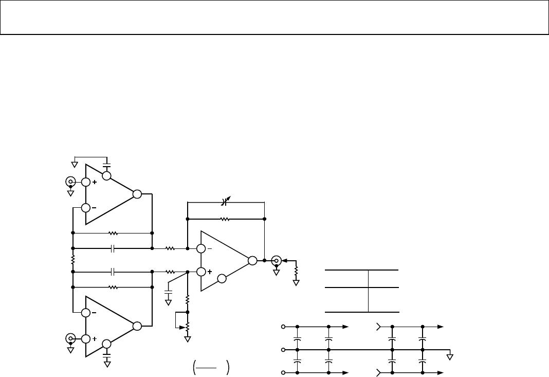
Figure 46. Noninverting Amplifier Connection Using Current Feedback
Compensation
Figure 47. Video Line Driver with a Flatness over Frequency Adjustment
LOW ERROR VIDEO LINE DRIVER
The buffer circuit shown in Figure 47 drives a back-terminated
75 Ω video line to standard video levels (1 V p-p), with 0.1 dB
gain flatness to 30 MHz and with only 0.0and 0.02% differential
phase and gain at the 4.43 MHz PAL color subcarrier frequency.
This level of performance, which meets the requirements for
high definition video displays and test equipment, is achieved
using only 5 mA quiescent current.
00880-044
FREQUENCY (MHz)
CLOSED-LOOP GAIN (dB)
1 10
–15
–12
–9
–6
–3
0
3
6
9
12
15
100
GAIN = –4
C
COMP
= 2pF
GAIN = –2
C
COMP
= 3pF
GAIN = –1
C
COMP
= 4pF
V
S
= ±15V
R
L
= 1k
R
F
= 1k
V
IN
= –30dBm
00880-045
FREQUENCY (MHz)
OUTPUT LEVEL (dB)
1 10
–47
–44
–41
–38
–35
–32
–29
–26
–23
–20
–17
100
±5V
±15V
V
IN
= –20dBm
R
L
= 1k
R
F
= 1k
GAIN = –1
C
COMP
= 4pF
00880-046
3
2
7
6
4
5
+
AD829
+15V
–15V
0.1µF
3pF
C
COMP
2k
2k
0.1µF
50
50k
50
50
COAX
CABLE
50
COAX
CABLE
V
IN
V
OUT
00880-047
3
2
7
6
5
4
+
AD829
+15V
0.1µF
30pF
C
COMP
–15V
0.1µF
300
300
75
75
75
50
COAX
CABLE
V
IN
V
OUT
OPTIONAL
2pF TO 7pF
FLATNESS
TRIM
AD829 Data Sheet
Rev. I | Page 16 of 20
HIGH GAIN VIDEO BANDWIDTH, 3-OP-AMP
INSTRUMENTATION AMPLIFIER
Figure 48 shows a 3-op-amp instrumentation amplifier circuit
that provides a gain of 100 at video bandwidths. At a circuit gain of
100, the small signal bandwidth equals 18 MHz into a FET probe.
Small signal bandwidth equals 6.6 MHz with a 50 load. The
0.1% settling time is 300 ns.
The input amplifiers operate at a gain of 20, while the output
op amp runs at a gain of 5. In this circuit, the main bandwidth
limitation is the gain/bandwidth product of the output amplifier.
Extra care should be taken while breadboarding this circuit
because even a couple of extra picofarads of stray capacitance at the
compensation pins of A1 and A2 will degrade circuit bandwidth.
Figure 48. High Gain Video Bandwidth, 3-Op-Amp In-Amp Circuit
00880-048
+15V
–15V
COMM
10µF
10µF
0.1µF
0.1µF
1µF
1µF
0.1µ
F
0.1µF
+V
S
–V
S
PIN 4
EACH
AM
PLIFIER
PIN 7
100Hz
1MHz
10MHz
64.6dB
44.7dB
23.9dB
INPUT
FREQUENCY CMRR
A1
AD829
2pF TO 8pF
SETTLING TIME
AC CMR ADJUST
3pF
3pF
1pF
1pF
2kΩ
200Ω
R
G
210Ω
1kΩ
2kΩ
200Ω
970Ω
50Ω
2kΩ
(G = 5)
5
3
2
6
DC CMR
ADJUST
3pF
(G = 20)
(G = 20)
A2
AD829
A3
AD848
+V
IN
+V
IN
CIRCUIT GAIN = + 1
4000Ω
R
G
5
5
2
3
6
5
3
2
6
Data Sheet AD829
Rev. I | Page 17 of 20
OUTLINE DIMENSIONS
Figure 49. 8-Lead Standard Small Outline Package [SOIC_N]
Narrow Body (R-8)
Dimensions shown in millimeters and (inches)
Figure 50. 8-Lead Plastic Dual In-Line Package [PDIP]
Narrow Body
(N-8)
Dimensions shown in inches and (millimeters)
CONTROLLING DIMENSIONS ARE IN MILLIMETERS; INCH DIMENSIONS
(IN PARENTHESES) ARE ROUNDED-OFF MILLIMETER EQUIVALENTS FOR
REFERENCE ONLY AND ARE NOT APPROPRIATE FOR USE IN DESIGN.
COMPLIANT TO JEDEC STANDARDS MS-012-AA
012407-A
0.25 (0.0098)
0.17 (0.0067)
1.27 (0.0500)
0.40 (0.0157)
0.50 (0.0196)
0.25 (0.0099)
45°
1.75 (0.0688)
1.35 (0.0532)
SEATING
PLANE
0.25 (0.0098)
0.10 (0.0040)
4
1
8 5
5.00 (0.1968)
4.80 (0.1890)
4.00 (0.1574)
3.80 (0.1497)
1.27 (0.0500)
BSC
6.20 (0.2441)
5.80 (0.2284)
0.51 (0.0201)
0.31 (0.0122)
COPLANARITY
0.10
COMPLIANT TO JEDEC STANDARDS MS-001
CONTROLLING DIMENSIONSARE IN INCHES; MILLIMETER DIMENSIONS
(IN
PARENTHESES) ARE
ROUNDED-OFF INCH EQUIVALENTS FOR
REFERENCE ONLY AND ARE NO
T APPROPRIATE FOR USE IN DESIGN.
CORNER LEADS MAY BE CONFIGURED AS WHOLE OR HALF LEADS.
070606-A
0.022 (0.56)
0.018 (0.46)
0.014 (0.36)
SEATING
PLANE
0.015
(0.38)
MIN
0.210 (
5.33)
MAX
0.150 (3.81)
0.130 (3.30)
0.115 (2.92)
0.070 (1.78)
0.060 (1.52)
0.045 (1.14)
8
1
4
5
0.280 (7.11)
0.250 (6.35)
0.240 (6.10)
0.100 (2.54)
BSC
0.400 (10.16)
0.365 (9.27)
0.355 (9.02)
0.060 (1.52)
MAX
0.430 (10.92)
MAX
0.014 (0.36)
0.010 (0.25)
0.008 (0.20)
0.325 (8.26)
0.310 (7.87)
0.300 (7.62)
0.195 (4.95)
0.130 (3.30)
0.115 (2.92)
0.015 (0.38)
GAUGE
PLANE
0.005 (0.13)
MIN

AD829ARZ-REEL

Mfr. #:
Manufacturer:
Analog Devices Inc.
Description:
Video Amplifiers IC HIGH Speed Low Noise
Lifecycle:
New from this manufacturer.
Delivery:
DHL FedEx Ups TNT EMS
Payment:
T/T Paypal Visa MoneyGram Western Union